
Apparatus of Multifunctional Integrating Flow Battery

a flow battery, multi-functional technology, applied in the direction of indirect fuel cells, electrochemical generators, transportation and packaging, etc., can solve the problems of quarter price of lithium batteries, inconvenient use in mobile devices or cars, and the price of electric vehicles is one of the main obstacles, so as to reduce storage costs, maximize efficiency, and save charging process

Inactive Publication Date: 2016-12-22
INST NUCLEAR ENERGY RES ROCAEC
View PDF6 Cites 34 Cited by
  • Summary
  • Abstract
  • Description
  • Claims
  • Application Information

AI Technical Summary

Benefits of technology

The present invention uses swappable flowing electrolytes to adjust power output and save charging process. It can be used in mobile or stationary power systems. The electrolytes can be directly replaced in electric vehicles for faster charging. The flow batteries can be quickly replaced and filled for testing. Multiple cell stacks, circulating pumps, and circulating pipelines are used to simultaneously charge and discharge power. Different operating strategies and control parameters allow for accurate control and security monitoring.

Problems solved by technology

It has been quite a long time on developing the flow battery, but a main drawback is the very huge volume and, hence, is not suitable to be used in a mobile device or a car.
It means the flow battery does not produce dendrite to rise problem on use life, Therefore, the flow battery can have almost unlimited use and save a lot of maintenance.
In the past, the price of the electric vehicle is one of the main obstacles on development.
Yet, if a flow battery is used in an electric car, only a quarter price of lithium battery needs.
Besides, because the electrolytes at two poles of the flow battery are stored separately, opportunity of mutual leakage is small and opportunity of self-discharge is also small with safety achieved, so that the energy can be stored for a long time.
Furthermore, voltage and current of the flow battery are unidirectional on charging / discharging power, but not bidirectional nor simultaneous.
Hence, the prior art does not fulfill all users' requests on actual use.

Method used


Image

  • Apparatus of Multifunctional Integrating Flow Battery
  • Apparatus of Multifunctional Integrating Flow Battery
  • Apparatus of Multifunctional Integrating Flow Battery

Examples


Embodiment Construction

[0012]The following description of the preferred embodiment is provided to understand the features and the structures of the present invention.

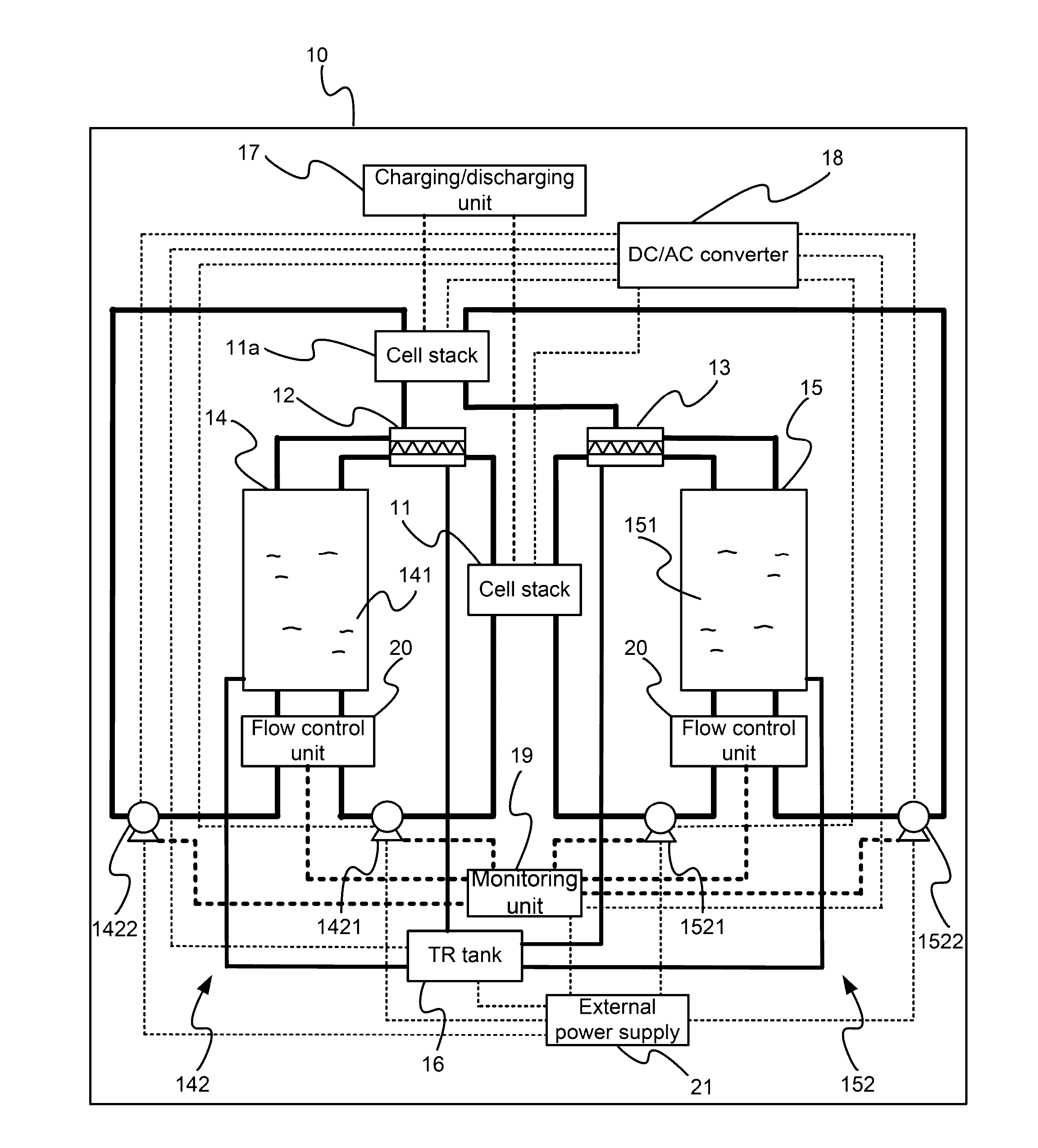
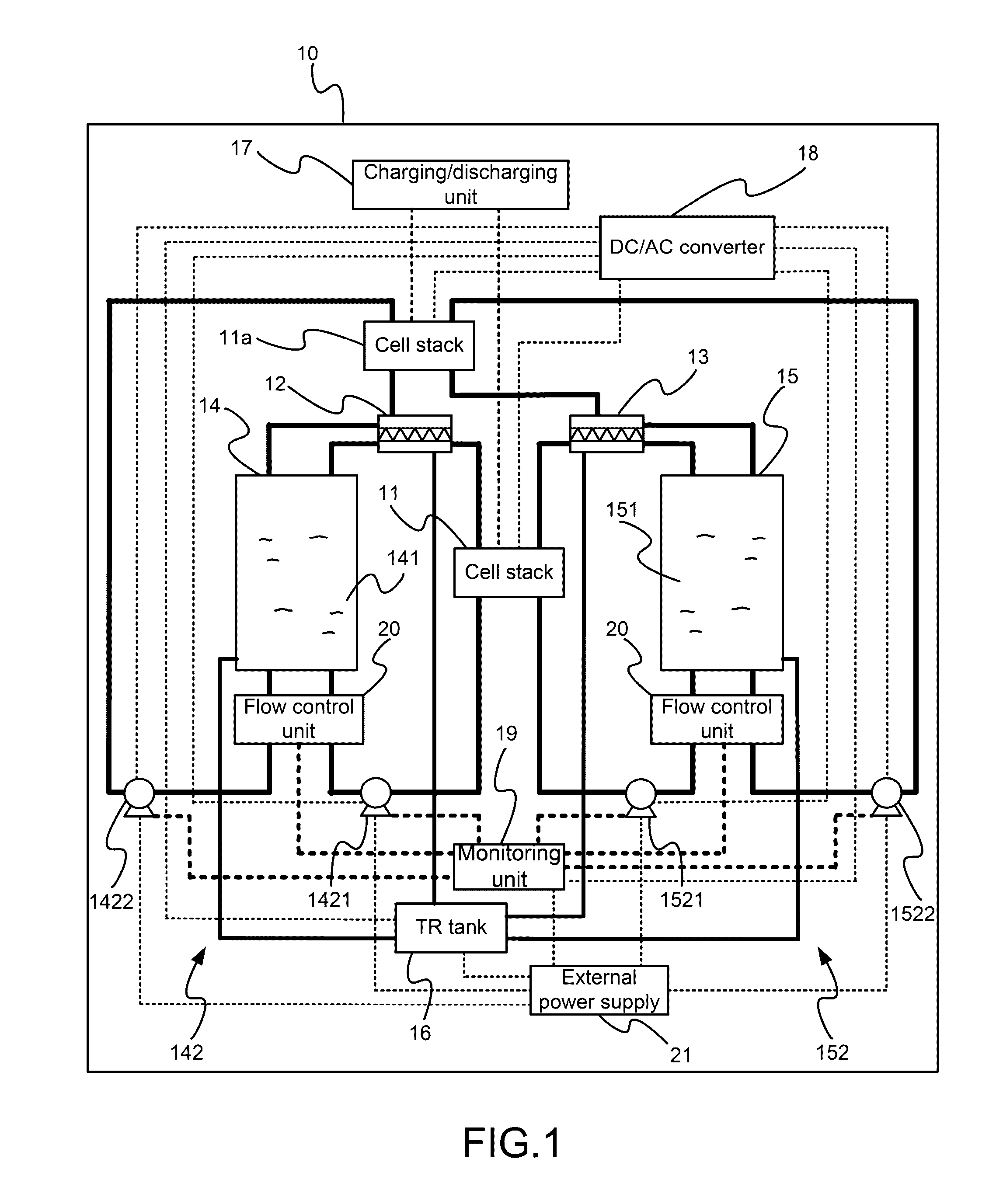
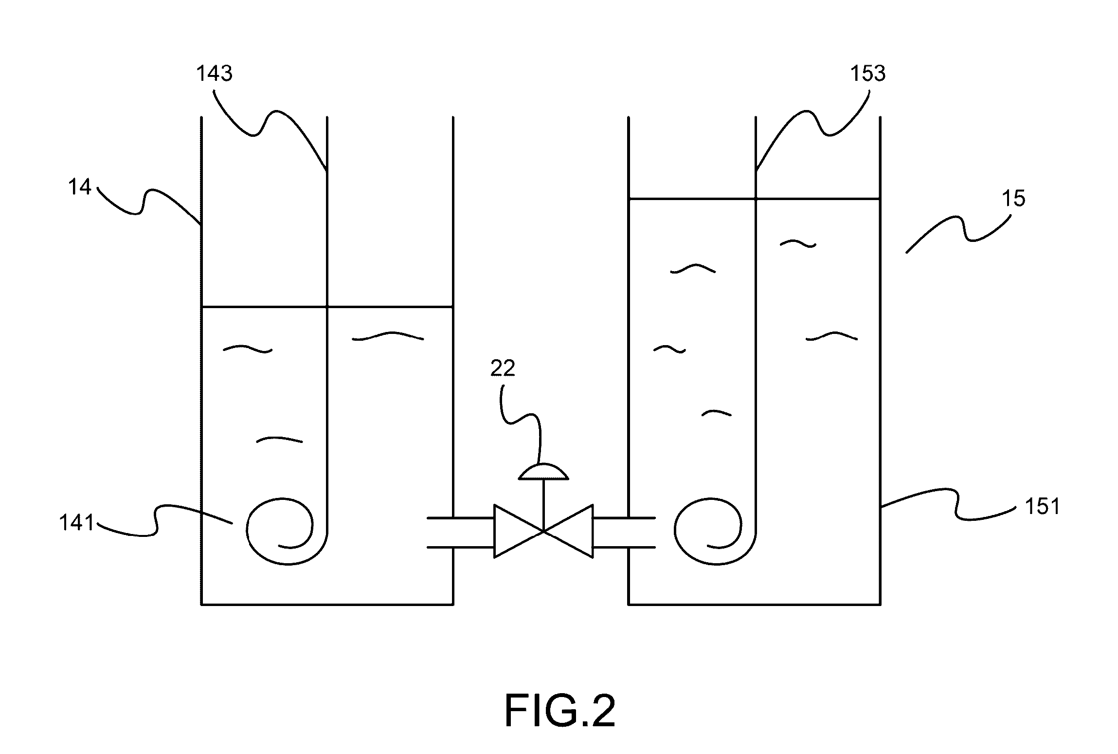
[0013]Please refer to FIG. 1 and FIG. 2, which are a structural view showing a preferred embodiment according to the present invention; and a view showing components of an anode and a cathode electrolyte tank. As shown in the figures, the present invention is an apparatus of multifunctional integrating flow battery, comprising two cell stacks 11,11a (or one of them), an anode heat exchanger 12, a cathode heat exchanger 13, an anode electrolyte tank 14, a cathode electrolyte tank 15, a temperature-retaining tank 16, a charging / discharging unit 17, a direct-current (DC) / alternating-current (AC) converter 18 and a monitoring unit 19.

[0014]The cell stacks 11,11a uses an anode electrolyte 141 and a cathode electrolyte 151 to generate and / or release DC power through electrochemical reactions and to output the anode electrolyte and the cathode elect...


PUM

PropertyMeasurementUnit
direct-current (aaaaaaaaaa
DC) poweraaaaaaaaaa
electrochemicalaaaaaaaaaa

Abstract

A device of flow battery is provided. The device comprises a cell stack, a heat exchanger, an anode electrolyte tank, a cathode electrolyte tank, a circulating pump, a temperature-retaining tank, a charging / discharging unit, a DC / AC converter and a monitoring unit. The device can be assembled in a container to form a portable flow battery to be integrated into a mobile power pack or a stationary power supply. Thus, the present invention is portable and swappable. The device can adjust power output according to flows and energy-storing statuses for saving cost and maximizing benefit. Household electricity is provided through the DC / AC converter. AC of a mains supply is converted into DC to charge power to an electric vehicle through the charging / discharging unit. Electrolytes in the anode and cathode electrolyte tanks can be directly replaced for finishing charging power in a short time.

Description

TECHNICAL FIELD OF THE INVENTION[0001]The present invention relates to flow battery; more particularly, relates to a portable power system of flow battery, where not only power-charging process is shortened and storage cost is reduced for maximizing efficiency; but also electrolytes used for an electric vehicle are directly replaced to charge power in a short time for effectively improving efficiency on charging power.DESCRIPTION OF THE RELATED ART[0002]A flow battery usually has two huge containers, which contains electrolytes to be pumped to cell stack. The stack has a membrane within. A forward reaction is processed across the membrane between two electrolytes to produce electricity, where, on charging power, a reverse reaction is processed. It has been quite a long time on developing the flow battery, but a main drawback is the very huge volume and, hence, is not suitable to be used in a mobile device or a car.[0003]In recent years, as following the development of renewable ener...

Claims


Application Information

Patent Timeline
Patent Type & Authority Applications(United States)
IPC IPC(8): H01M8/04H01M8/20H02J7/00H01M8/18
CPCH01M8/04007H01M8/188H02J7/007H02J7/0045H01M8/20Y02E60/50Y02T10/70
Inventor LU, YUNG-FANGHSIEH, CHIN-LUNGHSU, CHUNG-YAO
Owner INST NUCLEAR ENERGY RES ROCAEC
Learn More