
Bone healing probe

Inactive Publication Date: 2016-12-29
STRYKER EURO HLDG I LLC
View PDF55 Cites 1 Cited by
  • Summary
  • Abstract
  • Description
  • Claims
  • Application Information

AI Technical Summary

Benefits of technology

This patent describes a technology to continuously monitor conditions in the body to detect any complications related to bone healing. A special optical fiber is placed at the injury site and can measure various factors like temperature, pressure, and pH levels. The fiber can be secured in place using various methods during the healing process and can be removed non-invasively once monitoring is complete. The data collected from the fiber can be sent to a display or healthcare provider for further analysis and monitoring. Overall, this technology helps to provide early recognition of potential complications and allows for timely intervention in the treatment process.

Problems solved by technology

However, these current monitoring solutions are not suitable to predict either bone healing failures or normal bone formation.
As such, complications, such as nonunions and surgical site infections, are often recognized too late in clinical practice.
Nonunions are a serious complication that can result in psuedarthrosis or poor bone alignment, which may require surgical intervention.
Such nonunions may be caused by bone migration during the healing process, poor blood supply and infection, to name a few.
Surgical site infections (SSI) can occur in the wound created by an invasive surgical procedure and are a significant cause of healthcare-associated infections.
Such infections are a general health risk to the patient and can lead to non-unions in bone healing, particularly when left untreated.
However, current monitoring practices and techniques are inadequate.
However, all of these techniques have significant predictive limitations.
Radiography is a non-continuous technique that cannot predict load bearing properties of the fracture site and is potentially hazardous especially if overused.
Blood sampling and analysis is also non-continuous and valuable time for fighting an infection is often lost between blood draws.
Moreover, other than their predictive limitations, radiography, blood analysis, and other clinical diagnostic measures often require physically limited patients to make burdensome trips to a healthcare facility just to receive such testing.

Method used


Image

  • Bone healing probe
  • Bone healing probe
  • Bone healing probe

Examples


Embodiment Construction

[0033]When referring to specific directions in the following discussion of certain implantable devices, it should be understood that such directions are described with regard to the implantable device's orientation and position during exemplary application to the human body. Thus, as used herein, the term “proximal” means close to the heart and the term “distal” means more distant from the heart. The term “inferior” means toward the feet and the term “superior” means toward the head. The term “anterior” means toward the front of the body or the face and the term “posterior” means toward the back of the body. The term “medial” means toward the midline of the body and the term “lateral” means away from the midline of the body. Also, as used herein, the terms “about,”“generally” and “substantially” are intended to mean that deviations from absolute are included within the scope of the term so modified.

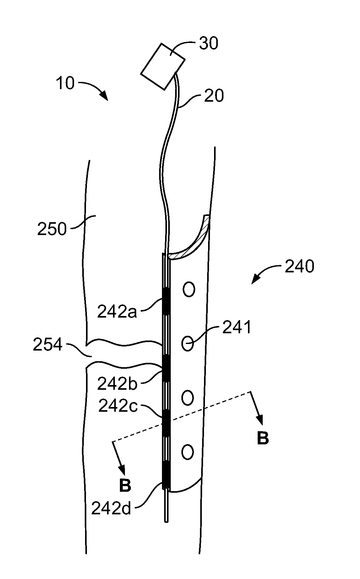
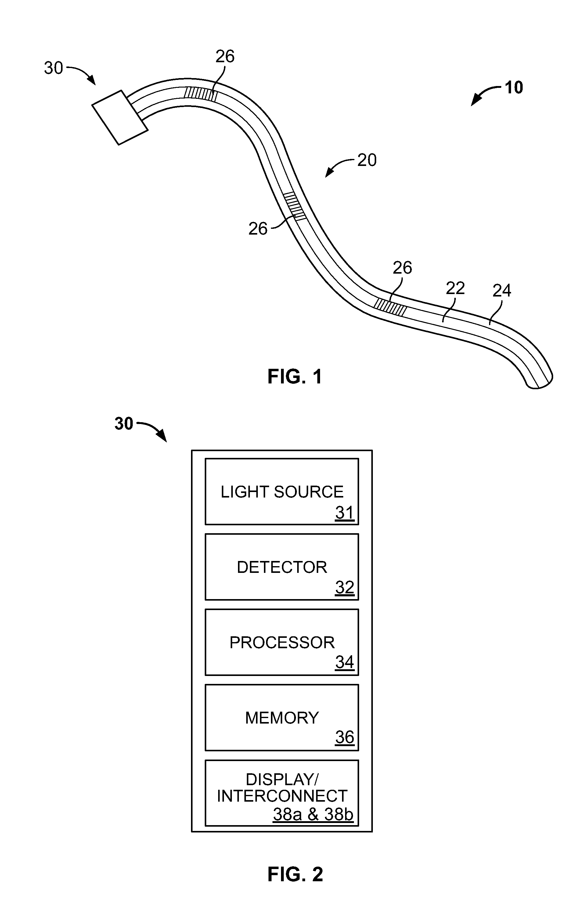
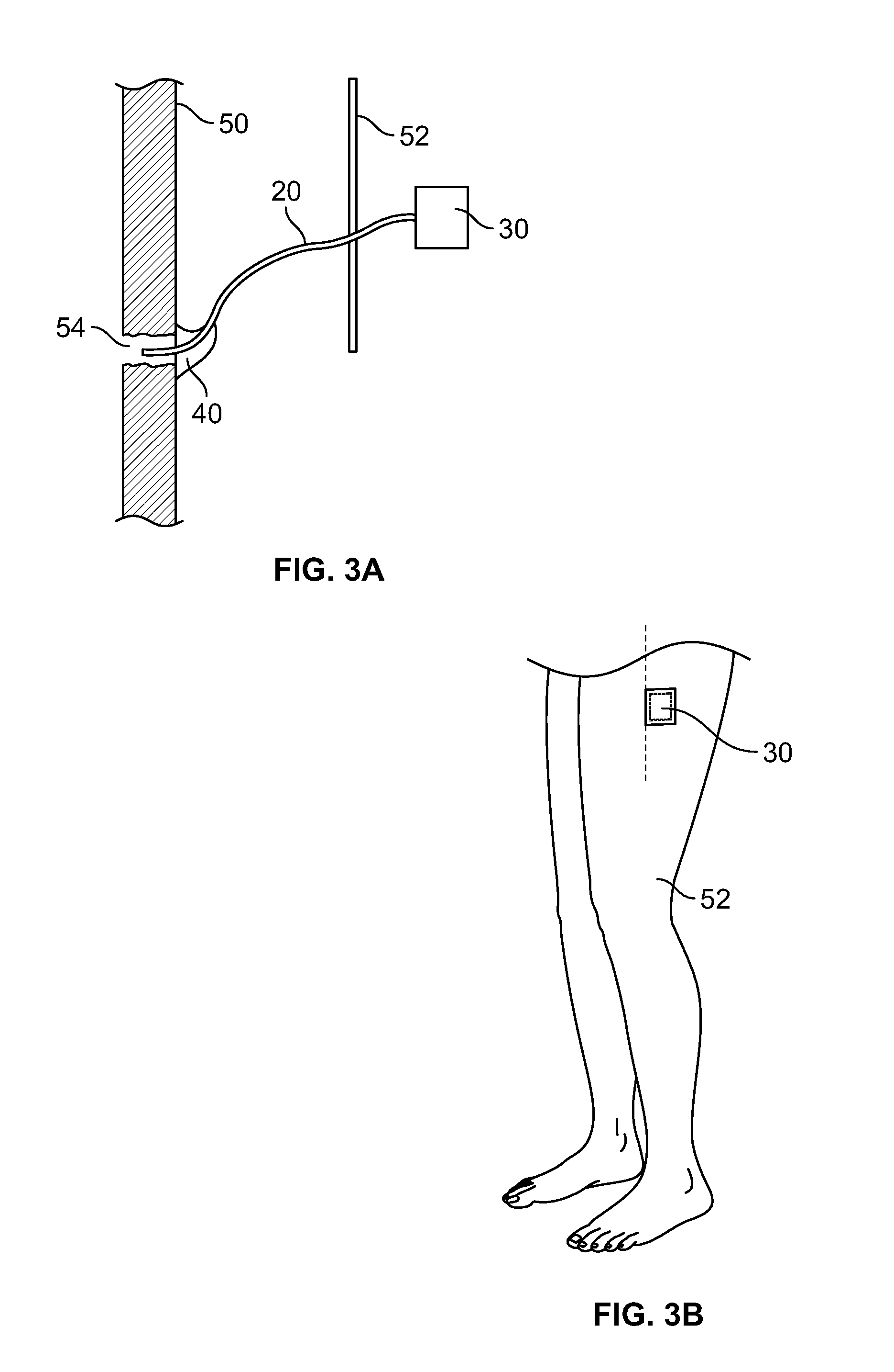
[0034]FIG. 1 depicts a bone healing probe system 10. Probe 10 generally includes an o...


PUM


Abstract

A bone healing monitoring system, which includes a probe configured to measure at least one physical condition. The probe includes an optical fiber and a control unit attached to the optical fiber. The system also includes a surgically implantable device having a channel extending along at least a portion of the implantable device and is configured to receive the optical fiber therein.

Description

CROSS-REFERENCE TO RELATED APPLICATIONS[0001]This application claims the benefit of the filing date of U.S. Provisional Patent Application No. 62 / 185,080 filed Jun. 26, 2015, the disclosure of which is hereby incorporated herein by reference.BACKGROUND OF THE INVENTION[0002]The proper healing of bone and tissue depends on multiple factors. Some of these factors include the age and biology of a patient, type and severity of the patient's injuries, and infections. Healing can be monitored through radiography, blood sample analysis and the like. However, these current monitoring solutions are not suitable to predict either bone healing failures or normal bone formation. As such, complications, such as nonunions and surgical site infections, are often recognized too late in clinical practice.[0003]Nonunions are a serious complication that can result in psuedarthrosis or poor bone alignment, which may require surgical intervention. Such nonunions may be caused by bone migration during th...

Claims


Application Information

Patent Timeline
IPC IPC(8): A61B5/00A61B17/60A61B17/80A61B5/08A61B5/103A61B5/01A61B5/145A61B17/72A61F2/30
CPCA61B5/0084A61B17/72A61B17/60A61B17/80A61F2/30A61B5/4504A61B5/01A61B5/14539A61B5/742A61B5/08A61B5/103A61B5/6878A61B5/0059
Inventor BUESCHER, ROBINNASSUTT, ROMAN
Owner STRYKER EURO HLDG I LLC
Learn More