Electronic Control Module and Method for Producing an Electronic Control Module

a technology of electronic control module and control module, which is applied in the direction of final product manufacturing, association of printed circuit non-printed electric components, fixed connections, etc., can solve the problems of difficult transmission fluid, and achieve the effect of saving installation space on printed circuit boards, advantageously relieved of loading, and stable and reliable electrical connections

Active Publication Date: 2017-01-05
ROBERT BOSCH GMBH
View PDF2 Cites 6 Cited by
  • Summary
  • Abstract
  • Description
  • Claims
  • Application Information

AI Technical Summary

Benefits of technology

[0009]For the application in the transmission oil it is advantageous if the electrical connection elements are electrically connectable to contacts on the printed circuit board in a welding process, and no connection pins project through onto the underside of the printed circuit board facing away from the component side of the printed circuit board. As a result, installation space requirement on the printed circuit board is advantageously saved by eliminating the plug-through connections. A welding process is advantageously provided according to the invention in order to weld a connection element of an electrical component mounted on the component side of the printed circuit board to a metallic web of the adapter, and as a result advantageously ensure a stable and reliable electrical connection between the connection element and the web. The orientation of the connection section of the connection element and the contact section of the metallic web is particularly advantageously parallel to the component side of the printed circuit board, wherein the contact section of the at least one metallic web and the connection section of the at least one connection element are arranged, when viewed in a direction perpendicular to the printed circuit board, resting one on top of the other in an overlapping region. This measure ensures that welding can be carried out with a laser perpendicular to the component side of the printed circuit board. Owing to the spatially extended overlapping region, the contact region between the contact section and the connection section is robust with respect to positional tolerances of the electrical component. The welding is preferably carried out with the laser in the overlapping region.
[0010]According to the invention, the electrical connection of the at least one electrical component to the printed circuit board is effected in that either the at least one metallic web or the at least one connection element, depending on which is arranged over the contact area, is placed in electrical contact with the at least one contact area by means of an electrically conductive material which is applied to the at least one contact area. Solder or a curable adhesive can be used as the electrically conductive material.
[0011]The electrical connection, produced by means of the electrically conductive material, to the at least one contact area of the printed circuit board is particularly advantageously relieved of loading by the welded connection between the at least one connection element and the at least one metallic web and by the mechanical securement of the adapter to the printed circuit board which is independent of the electrical connection to the printed circuit board. Thermal stresses and vibrational loading can therefore be absorbed by means of the stable mechanical attachment of the adapter, with the result that lateral forces and vertical forces are kept away from the connection which is produced by means of the electrically conductive material. The forces are advantageously absorbed by the printed circuit board by means of the holding body of the adapter. Therefore, the loading on the soldered point can be relieved, in particular in the event of solder being used as electrically conductive material.
[0012]Advantageous refinements and developments of the invention are made possible by the features contained in the dependent claims.
[0013]The electronic control module advantageously has an adapter with a holding body which has at least one attachment pin which is inserted into an insertion opening in the printed circuit board. The attachment pin can be clamped, for example, in the insertion opening in the printed circuit board. In this context, the attachment pin simultaneously closes the insertion opening in the printed circuit board. Since the attachment pin in the insertion opening has, in contrast to a pin in a via, no electrical function, no openings which contain electrically conductive parts are advantageously contained on the underside of the printed circuit board. The attachment pin can advantageously be embodied in one piece with the holding body.
[0014]The holding body of the at least one adapter can be fabricated from plastic. The adapter can be manufactured, for example, in a cost-effective fashion as a simple injection molded part in which the metallic web is encapsulated by injection molding with the plastic of the holding body. The attachment pin of the holding body can be produced simultaneously with the encapsulation of the metallic web by injection molding on the holding body.

Problems solved by technology

The arrangement in the transmission fluid is very challenging for the design technology and connecting technology of the components on the carrier of the electronic control module, since the electrical connections have to be able to withstand high alternating temperature stresses as well as the transmission fluid with metal swarf contained therein in an unfavorable case.
A disadvantage of this connecting technology for the application in transmission oil is that the connection elements project through onto the underside of the printed circuit board and covers and protective measures are therefore necessary on the underside in order to prevent depositing of metal swarf and resulting short-circuits.

Method used


Image

  • Electronic Control Module and Method for Producing an Electronic Control Module
  • Electronic Control Module and Method for Producing an Electronic Control Module
  • Electronic Control Module and Method for Producing an Electronic Control Module

Examples


Embodiment Construction

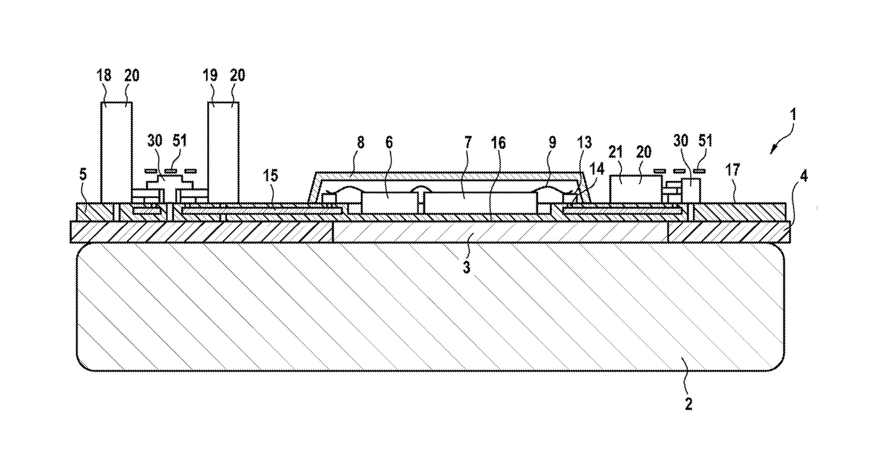
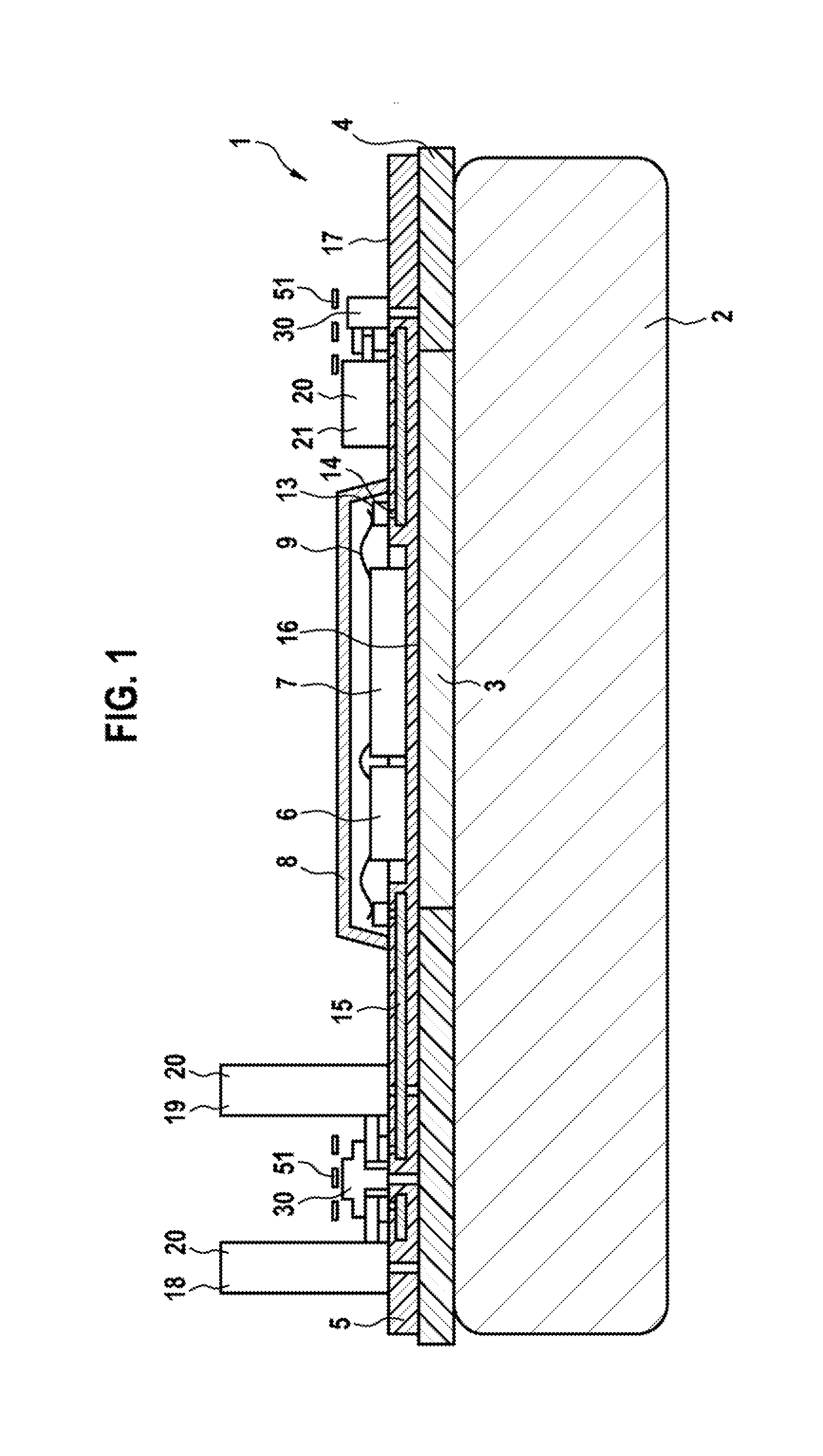
[0045]FIG. 1 shows a cross section through an electronic control module 1 for a motor vehicle transmission. The electronic control module 1 has a printed circuit board 5 as a carrier of the construction and connection technology. The printed circuit board is a rigid printed circuit board, for example a printed circuit board of an FR4 design or of a higher value, that is to say, for example, a printed circuit board made of glass-fiber-reinforced epoxy resin. The printed circuit board has, in its interior, at least one or more parallel layers provided with conductor tracks 15. The connection of the conductor tracks of different layers is made via intermediate connections (VIAs), which are also referred to as vias. The printed circuit board 5 has a component side 17 and an underside 16 facing away from the latter. The conductor tracks 15 are also electrically connected to contact areas 13 of the component side 17 of the printed circuit board 5 via intermediate connections 14. The compo...


PUM


Abstract

An electronic control module includes a printed circuit board and an electrical component. The circuit board has a contact area arranged on a component side. The electrical component has an electrical connection element with a connection section running parallel to the component side and is electrically connected to the contact area. An adapter is arranged on the circuit board independently of the electrical component and has a holding body fastened to the circuit board outside the contact area and a metal web. The web is arranged on the holding body and has a contact section running parallel to the component side. The contact section and the connection section lie atop another and are welded to one another in a covering area. The web or the connection element makes electrical contact with the contact area by an electrically conductive material applied to the contact area.

Description

PRIOR ART[0001]The invention relates to an electronic control module, in particular for a transmission controller, and to a method for producing such an electronic control module.[0002]In motor vehicle engineering, electronic control modules which can be arranged on the transmission and in the transmission fluid are used for actuating the transmission. The control modules can have, for example, electrical components such as plugs, sensors, actuators, at least one encapsulated control unit (TCU, transmission control unit) and, if appropriate, further components which are attached to a central carrier and are subjected to the transmission fluid. The arrangement in the transmission fluid is very challenging for the design technology and connecting technology of the components on the carrier of the electronic control module, since the electrical connections have to be able to withstand high alternating temperature stresses as well as the transmission fluid with metal swarf contained the...

Claims


Application Information

Patent Timeline
Patent Type & Authority Applications(United States)
IPC IPC(8): H05K3/32H05K1/11H05K1/18H05K1/02
CPCH05K1/113H05K3/328H05K3/3421H05K5/0082H05K2201/09063H05K2201/10204H05K2201/1028H05K2201/10628H05K2201/10962H05K2203/107Y02P70/50H01R12/51H01R12/57H01R12/62H05K1/0206H05K1/115H05K1/181H05K3/30H05K3/32H05K3/321H05K3/326
Inventor LISKOW, UWE
Owner ROBERT BOSCH GMBH
Why Eureka
Try Eureka