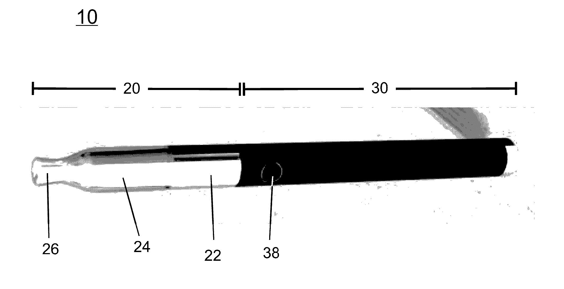
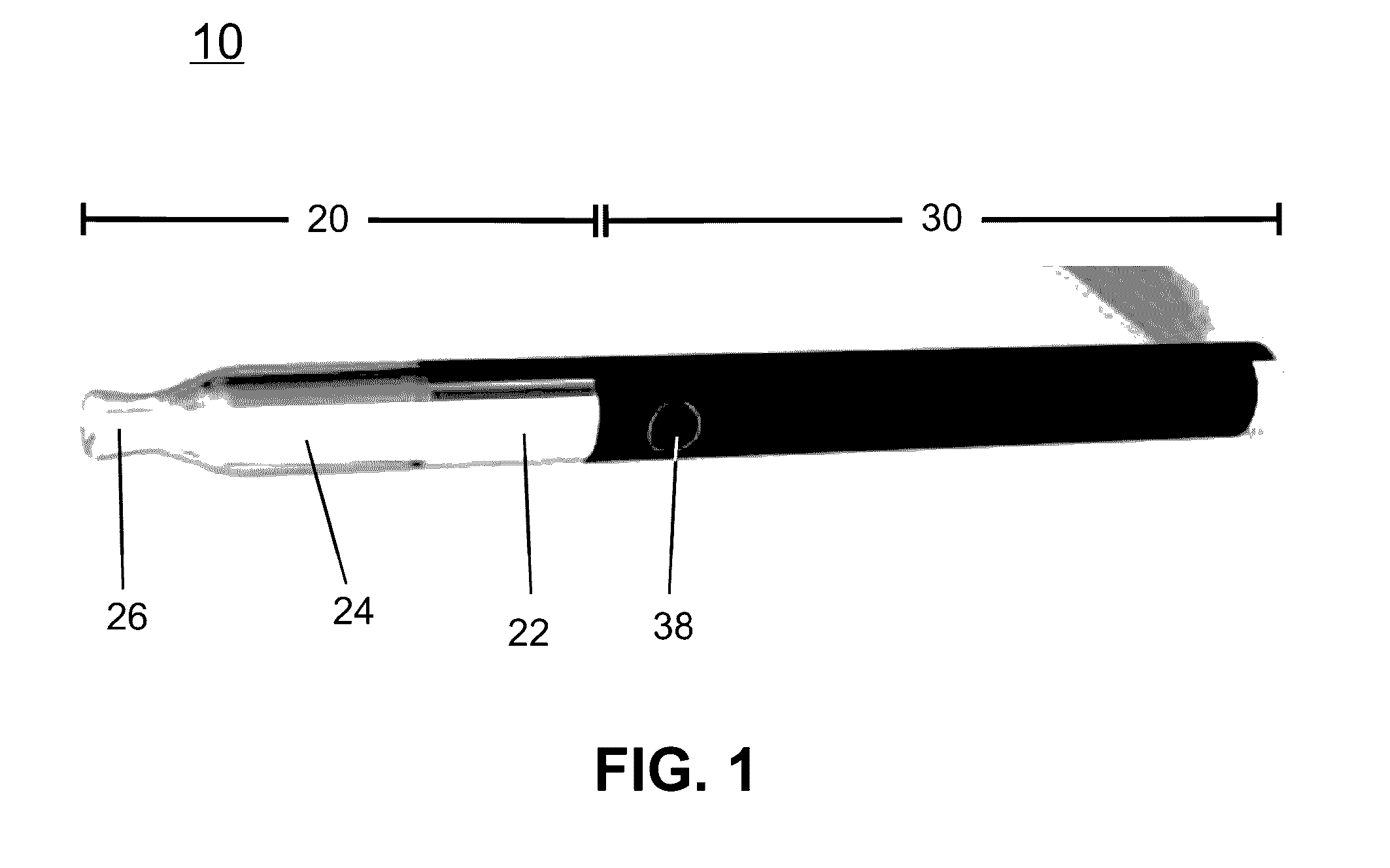
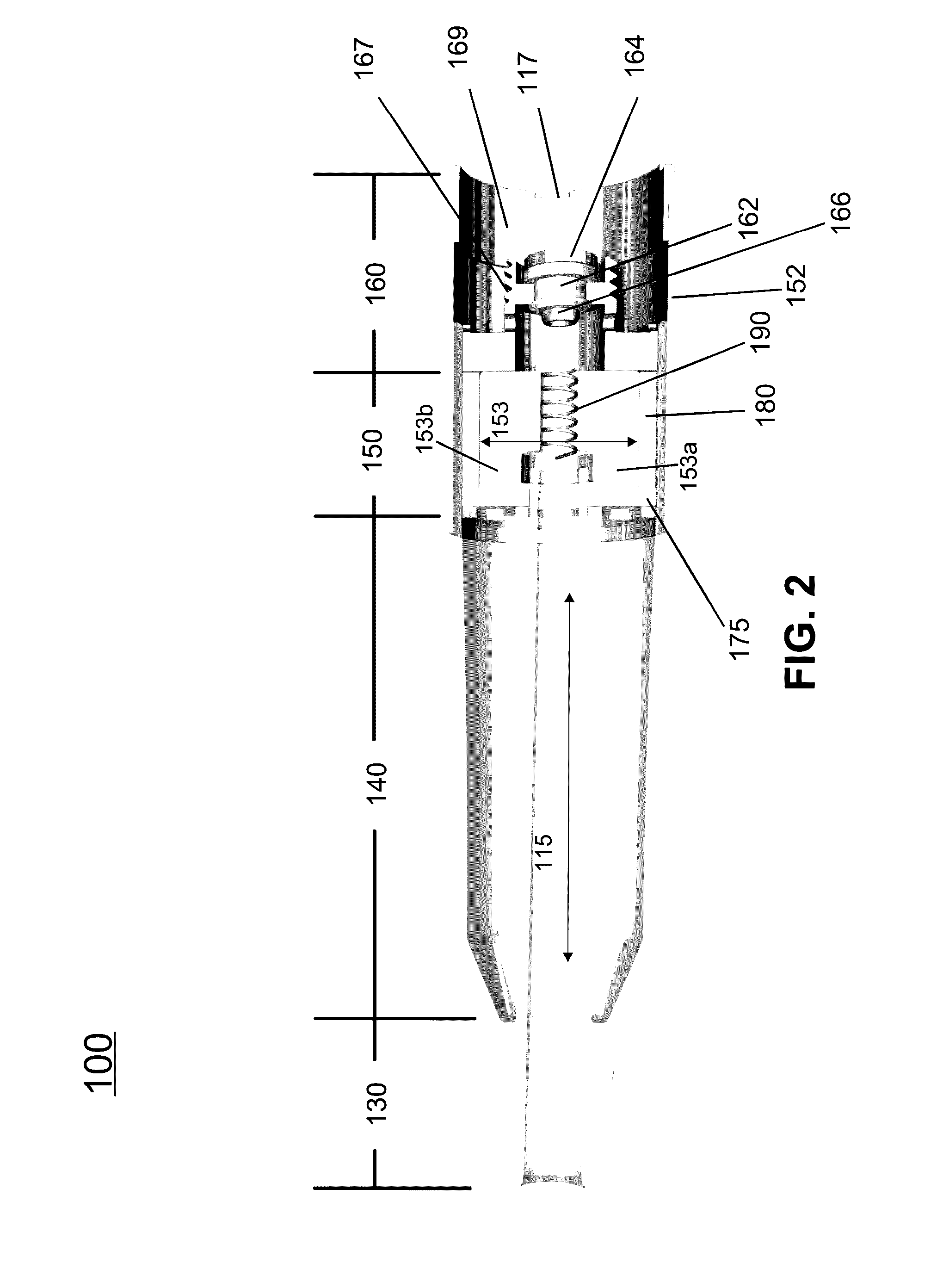
Vaporizer tank with atomizer

a technology of atomizer and vaporizer, which is applied in the field of electronic vaporization devices, can solve the problems of shortening increasing the power may come at the expense of portability of the device, and reducing so as to increase the quality of vaporization, prolong the life of the battery, and reduce the cost of vaporization.

Active Publication Date: 2017-01-19
NJOY LLC
View PDF13 Cites 46 Cited by
  • Summary
  • Abstract
  • Description
  • Claims
  • Application Information

AI Technical Summary

Benefits of technology

[0004]Embodiments of the present disclosure may provide a relatively more efficient atomizer, e.g., for delivering an equivalent or comparable amount of vapor at a lower power level, which may extend the life of the battery and / or allow use of a smaller battery. Embodiments of the present disclosure include vaporizing devices that may deliver a greater amount and / or higher quality vapor using a smaller or otherwise more efficient battery. Devices according to the present disclosure may be relatively more compact and portable.

Problems solved by technology

But higher power also may lead to undesirable effects.
For example, driving the battery to deliver more power can shorten the life of the battery.
While larger batteries may be capable of increasing power, the increased power may come at the expense of portability of the device since the overall size and weight of the device is increased.
Delivering more power to the atomizer also can lead to intermittent drying of the wick and / or overheating, which in turn can cause degradation of the liquid.
Degradation products of the liquid can result in poor taste and / or may be harmful to health.
The risks of wick drying and overheating are expected to increase as users apply more power.

Method used


Image

  • Vaporizer tank with atomizer
  • Vaporizer tank with atomizer
  • Vaporizer tank with atomizer

Examples


example 1

[0043]Devices according to the present disclosure were tested at different power levels and compared to a commercially-available device of a different design. FIG. 7 shows a bar graph comparison of devices A, B, and C, wherein devices B and C included a tank 100 that separates the atomizer assembly from the liquid reservoir as described above. Device A included a different type of tank, with the atomizer assembly submerged in liquid. The same liquid was used in each device (a 50-50 mixture of propylene glycol and glycerin, with 15 mg / ml nicotine and additional flavorings). Device A was operated at 11 W, device B was operated at 9.1 W, and device C was run at 10.5 W.

[0044]The vapor output (measured as TPM, in mg / puff, on the y-axis of FIG. 7) measured shows that devices B and C generated more vapor per amount of power, relative to device A. The performance of device B was nearly equivalent to the performance of device A, with device B run at a lower power level. The performance of de...

example 2

[0045]The performance of a device (a) according to the present disclosure (e.g., tank 100 described above) was compared to the performance of several commercially-available devices (b)-(f), each comprising an atomizer assembly submerged in liquid. The tanks had the following resistances: device (b), 1.5Ω; device (c), 1.6Ω; device (d), 0.5Ω; device (e), 1.2Ω; device (f), 1.8Ω. The same liquid was used in each device (a 50-50 wt. mixture of propylene glycol and glycerin, with 15 mg / ml nicotine and additional flavorings). Each device was operated at a series of different power levels and the mass of vapor generated (TPM, in mg / puff) was measured. FIG. 8 shows that device (a) generated a higher amount of vapor at a given power level in comparison to devices (b)-(f).


PUM


Abstract

A tank of a vaporizing device is described, wherein the tank may comprise an atomizer and a reservoir for containing a liquid adjacent to the atomizer. The atomizer may include a wick and a heating element, wherein the tank includes a barrier that separates the wick from liquid in the reservoir. The barrier may be at least partially permeable to allow for transfer of liquid from the reservoir to the wick for vaporization. The tank may include a connector coupled to the atomizer and configured to electrically connect the atomizer to a power supply.

Description

TECHNICAL FIELD[0001]The present disclosure generally relates to electronic vaporization devices, components thereof, and related methods of use.BACKGROUND[0002]Electronic Nicotine Delivery Systems (ENDS) are currently available as alternatives to combustion cigarettes. Examples of ENDS devices include electronic vaporizers, such as, e.g., disposable and rechargeable electronic cigarettes, electronic vaporizers / vape pens, and advanced personal vaporizers (APVs). Some ENDS devices include an atomizer with a reservoir that contains a liquid, and a wick in contact with the liquid in the reservoir. Typically, the atomizer has a heating element and a power source for providing heat to vaporize the liquid. The atomizer is usually enclosed in a metal housing with holes that expose the wick to the liquid in the reservoir. The atomizer assembly is located at the end of the reservoir and is submerged in liquid in order for the wick to replenish vaporized liquid.[0003]Vapor output is a charact...

Claims


Application Information

Patent Timeline
Patent Type & Authority Applications(United States)
IPC IPC(8): A24F47/00H05B1/02H05B3/00A24F40/10A24F40/42A24F40/485
CPCA24F47/008H05B1/0244H05B3/0014A24F40/10A24F40/42A24F40/485
Inventor SCHULER, DAVIDMILLER, RYAN
Owner NJOY LLC
Why Eureka
Try Eureka