Microstructured Surface

a microstructured surface and surface technology, applied in the field of microstructured surfaces, can solve the problems of difficult to manufacture similar arrangements, reducing the possibility of forming round microstructured bumps, and increasing time consumption and cost, so as to facilitate pressure distribution and increase the surface area

Inactive Publication Date: 2017-01-19
BVW HLDG +1
View PDF3 Cites 65 Cited by
  • Summary
  • Abstract
  • Description
  • Claims
  • Application Information

AI Technical Summary

Benefits of technology

[0046]In a further advantageous embodiment, said undulating surface defining said first set of micro features includes rounded peaks that facilitate pressure distribution across said substrate.
[0047]In

Problems solved by technology

The random bumps and microstructures of the rose petal, however, have made it difficult to attempt to manufacture similar arrangements.
The limitation using this method is that stereolithography can only create angled structures at a 57 degree angle, thus eliminating the option for forming round microstructured bumps.
However, the processes used required numerous materials and multiple steps, which is more time consuming and expensive.
Usin

Method used


Image

  • Microstructured Surface
  • Microstructured Surface
  • Microstructured Surface

Examples


first embodiment

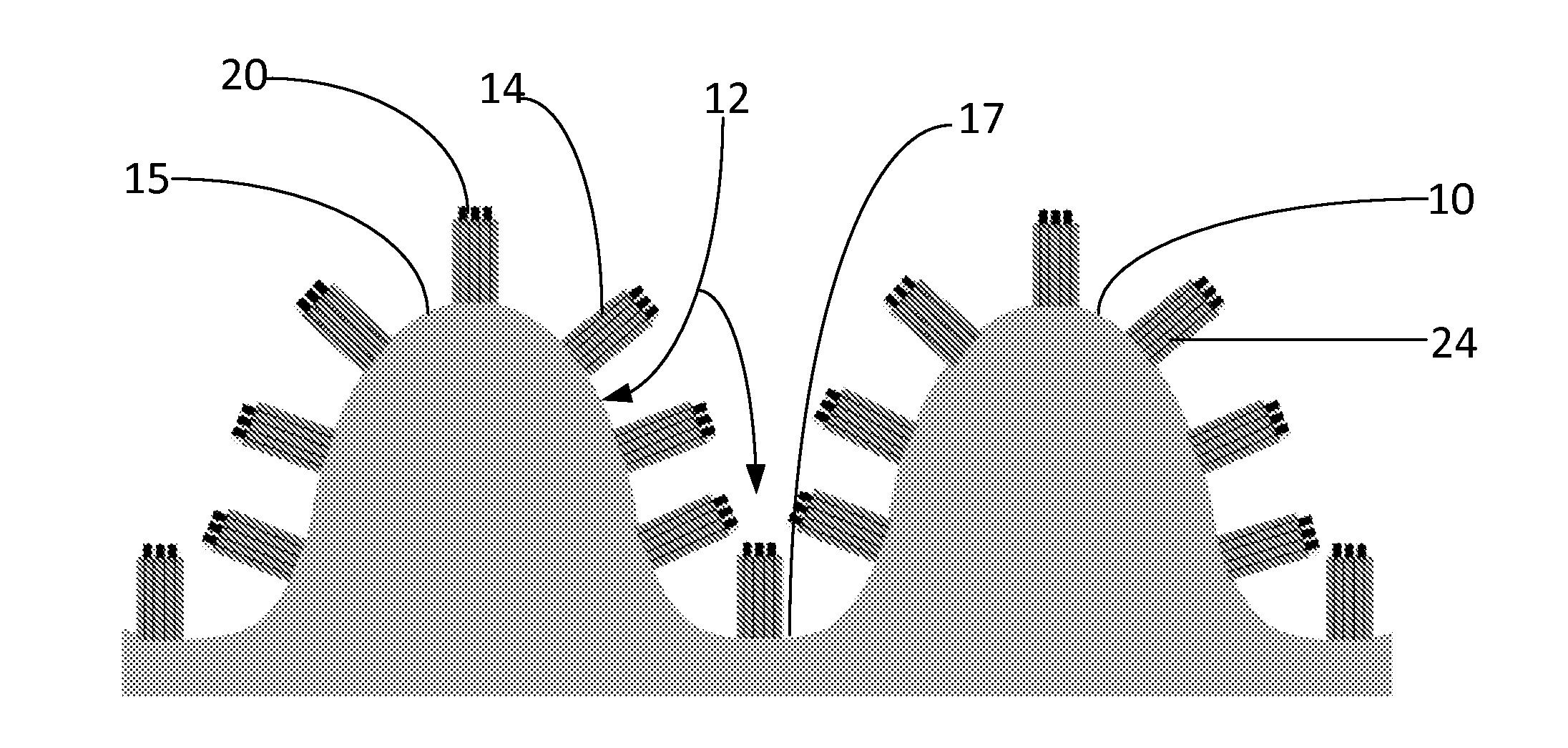
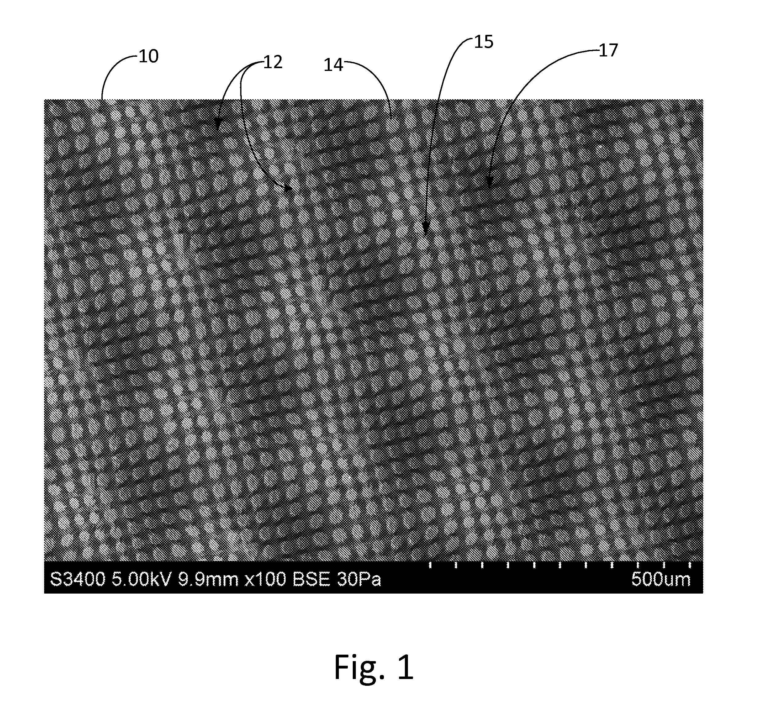
[0077]Referring to FIG. 1, a microstructure arrangement according to the present invention is shown comprising a substrate, designated generally as 10. In the illustrated embodiment, substrate 10 has an undulating surface forming a series of rounded peaks and valleys that produce a continuously curving surface across at least a portion of substrate 10. The undulating surface of substrate 10 defines a first set of micro features, designated generally as 12. In FIG. 1, substrate 10 is constructed and arranged to focus on a series of rounded knobs forming peaks 15 projected upwardly from the surface with associated valleys 17 disposed between peaks 15.

second embodiment

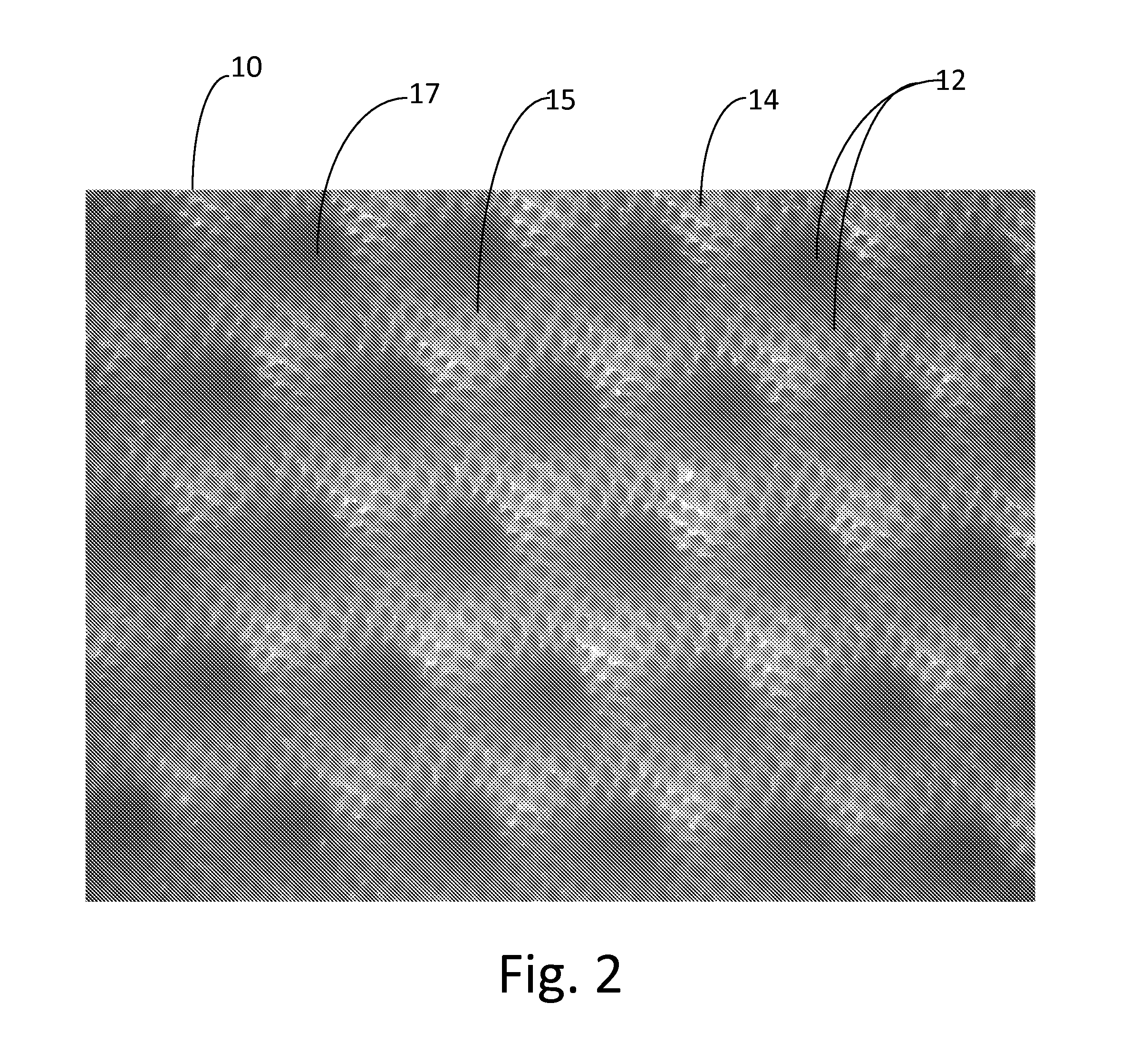
[0078]In a second embodiment shown in FIG. 2, the inverse arrangement is shown in which substrate 10 is constructed and arranged to focus on a series of rounded cavities forming valleys 17 extending inwardly into substrate 10 as the dominant feature with the associated peaks 15 disposed between valleys 17. In both embodiment, the surface of substrate 10 is continuously curving throughout the undulating surface pattern area.

[0079]According the present invention and as illustrated in several of the embodiments, the undulating surface of substrate 10 has a repetitive oscillation of rounded, non-flat curvatures. The curvatures of the substrate surface can be described by mathematical formulas incorporating trigonometric functions sine, cosine, tangent or exponential and power series functions. These mathematical formulas are used in computer aided design and computer aided manufacturing software to create micro surfaces using rapid prototyping, milling, electrical discharge machining or...


PUM

PropertyMeasurementUnit
Lengthaaaaaaaaaa
Lengthaaaaaaaaaa
Lengthaaaaaaaaaa

Abstract

A substrate having an undulating surface forming a series of rounded peaks and valleys that produce a continuously curving surface across at least a portion of the substrate. The undulating surface defines a first set of micro features. A second set of micro features molded on the first set of micro features. The substrate is a compression molded polymeric material in which the first and second sets of micro features are formed on the substrate during a single molding step, and wherein the first and second sets of micro features cooperate to increase the surface area and affect at least one of adhesion, friction, hydrophilicity and hydrophobicity of the substrate.

Description

BACKGROUND OF THE INVENTION[0001]1) Field of the Invention[0002]The present invention relates to microstructured surfaces, and more particularly to a substrate having increased surface area through a hierarchical arrangement of multiple shapes and sizes of micro features providing a surface that is superhydrophobic while having enhanced sliding friction and adhesion when placed against liquid covered surfaces.[0003]2) Description of Related Art[0004]Biomimetics, or the study of systems in nature, has become an increasingly popular source of inspiration to solve complex human issues. In order to create materials with specific properties, many research groups have identified plants or animals in nature that exhibit the desired properties, and then studied the underlying mechanisms.[0005]Studies revolving around plants and their petal effects have shown to portray a superhydrophobic effect, where round droplets that slide easily on the surface are maintained, and various levels of adhe...

Claims


Application Information

Patent Timeline
IPC IPC(8): A61B17/00B29C59/00B29C59/02
CPCA61B17/00B29C59/022A61B2017/0096B29L2007/001B29C59/005B29K2995/0092B29K2995/0093B29C59/025B29C2059/023A61B2017/00938A61B2017/00951A61B2017/00995A61B2017/00526A61B2017/00858B08B17/065
Inventor HULSEMAN, RALPH A.TACKETT, II, KENNETH N.MCPHERSON, CAMERON L.HULSEMAN, CARL L.TRIP, ROELOFMILBOCKER, MICHAELBLUECHER, LUKAS GRAF
Owner BVW HLDG
Why Eureka
Try Eureka