
Medical Balloon

a technology of balloons and balloons, applied in the field of medical balloons, can solve the problems of mechanical reduced efficacy of prior art iabs in inclined patients, damage to blood cells, etc., and achieve the effect of enhancing the afterload and less resistan

Active Publication Date: 2017-01-19
BRUNEL UNIVERSITY
View PDF3 Cites 22 Cited by
  • Summary
  • Abstract
  • Description
  • Claims
  • Application Information

AI Technical Summary

Benefits of technology

[0051]As discussed above, the inventor observed that when a conventional IAB is operated at an angle, such as when a patient is inclined to the preferred semi-recumbent position, the resulting hydrostatic pressure difference between the ends of the balloon will cause such a conventional IAB to inflate progressively from the second end towards the first end (i.e. from top to bottom). This difference in hydrostatic pressure, Δp, is given by:
[0053]h=vertical difference in height between the two ends of the IAB
[0054]The preferred direction of IAB deflation is from tip to base; and similarly, the preferred direction of the decompression action is also from the tip to the base of the balloon. The mechanical effect of balloon deflation is understood as follows: as the balloon begins to deflate, it generates an expansion (decompression) wave that runs towards the ascending aorta. By its nature, this wave pulls an amount of blood away from the heart (similar to drawing fluid through a straw).
[0055]The inventor observe

Problems solved by technology

As such, it is common for conventional prior art IABs to provide reduced efficacy in the inclined patient.
One particular issue with IAB treatment is the possibility of mechanical damage to blood cells.
If these or their rates are too extreme, it may result in damage to the blood cells.
There is also a risk that blood cells may be trapped between the IAB and a vessel wall if the IAB is operated to occlude the passage or vessel.

Method used


Image

  • Medical Balloon
  • Medical Balloon
  • Medical Balloon

Examples


Embodiment Construction

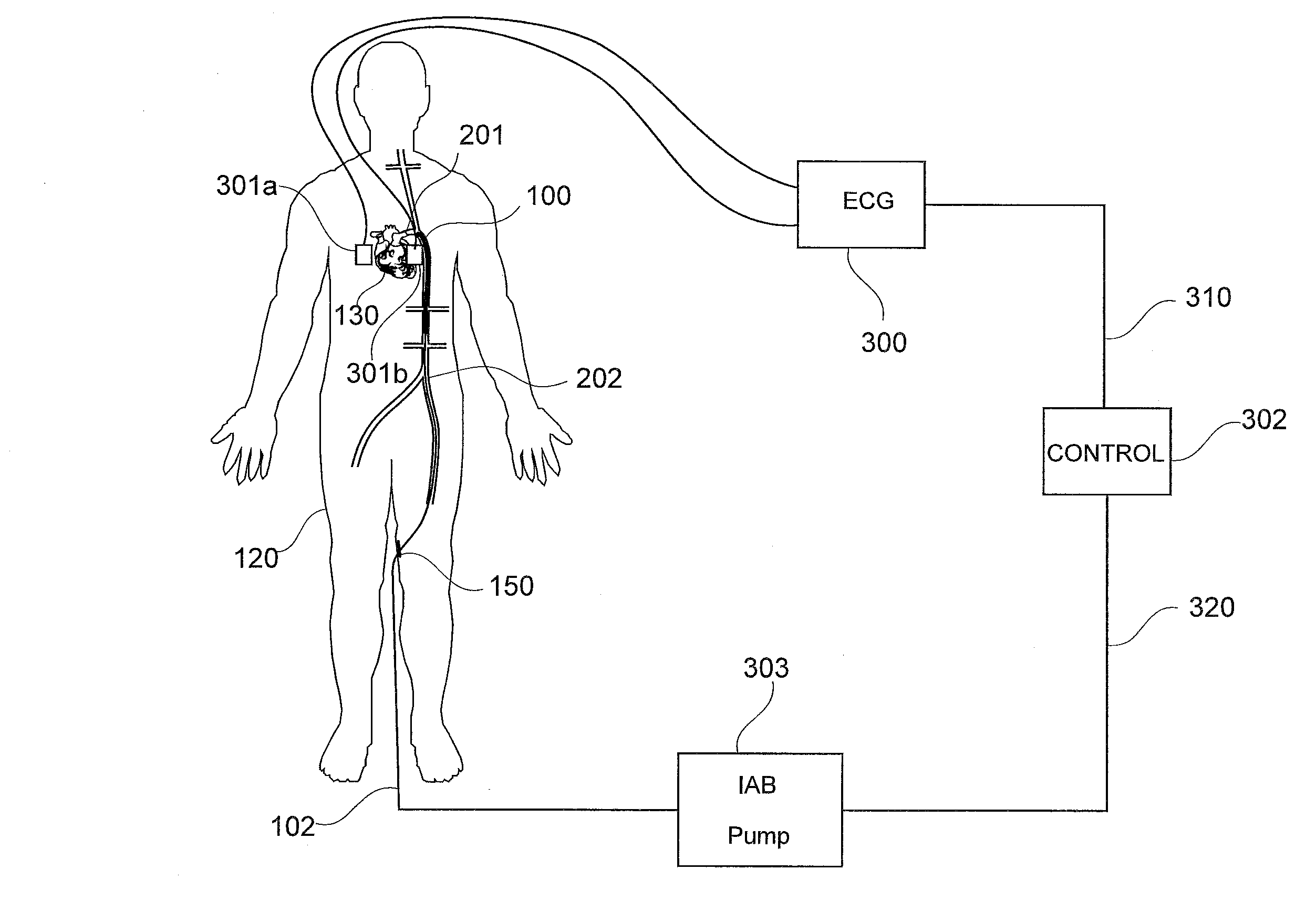
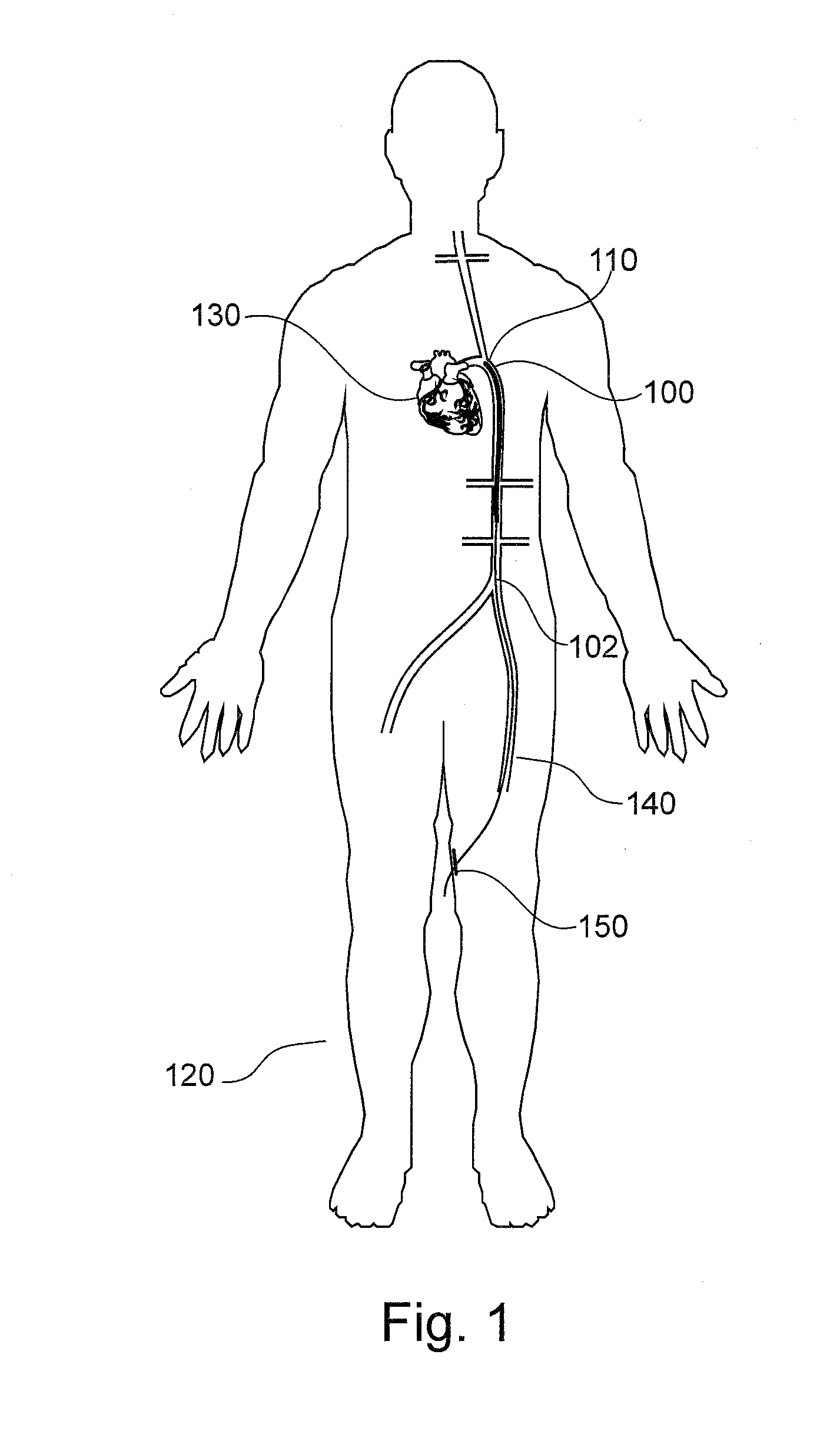
[0070]FIG. 1 shows a medical balloon in the form of an IAB 100 according to a first embodiment. The IAB 100 is shown within the aorta 110 of a human patient 120. The IAB 100 is connected to a catheter in the form of a flexible pipe 102.

[0071]In this embodiment, the balloon is made of a polymeric material and the flexible catheter 102 is typically made from a grade of polyurethane or other polymer of similar properties.

[0072]The aorta 110 extends from the heart 130 of the patient 120 toward a groin region 140 of the patient 120 (the aorta 110 also supplies other portions of the patient 120 with oxygenated blood but, for clarity, FIG. 1 only shows the aorta 110 descending down to the groin area 140 of the patient 120).

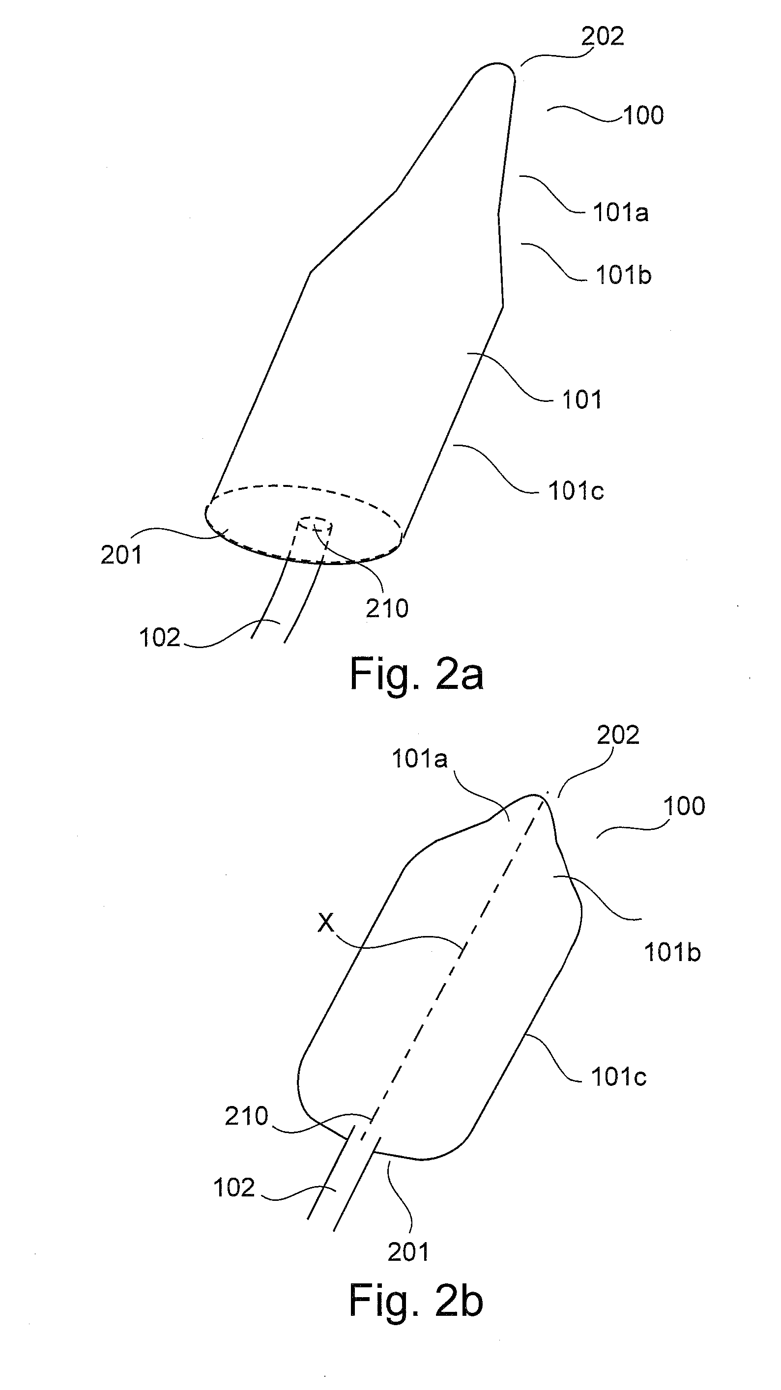
[0073]To position the IAB 100 inside the aorta 110 close to the heart 130, a clinician (not shown) typically makes an incision 150 in the groin area 140 and uses the catheter 102 to guide the IAB 100 until the top end (see FIGS. 2a and 2b, which show the top end of the b...


PUM


Abstract

A medical balloon for a balloon pump is disclosed. The medical balloon has a first end and a second end and a port at one of the ends for engaging a catheter for receiving an inflation fluid into the balloon. The balloon has one or more exterior walls defining, when the balloon is inflated at substantially a standard operating pressure, a taper along at least a part of the length of the balloon. The taper has two or more consecutive tapering sections, each tapering section having a different, substantially constant, angle of tapering. The balloon is substantially asymmetrical about a mid-point between the first and second ends when inflated.

Description

CROSS-REFERENCE TO RELATED APPLICATIONS[0001]This application claims priority to GB Patent Application No. 1512389.6 filed on Jul. 15, 2015, the complete disclosure of said application is hereby incorporated by reference.FIELD OF THE INVENTION[0002]The present invention relates to medical balloons and in particular (but not exclusively) to Intra-Aortic Balloons (IABs) for use in intra-aortic balloon pumping with humans or animals.BACKGROUND TO THE INVENTION[0003]Medical balloons are used in a number of areas in treatment of humans and animals. For example, balloons are used during delivery of medical devices such as stents. A deflated balloon is positioned inside a stent and the package is positioned in a lumen that the stent is to support. The balloon is inflated which causes the stent to expand into a deployed state. The balloon can then be deflated and removed, leaving the deployed stent in place.[0004]Embodiments of the present invention concern medical balloons that are designe...

Claims


Application Information

Patent Timeline
IPC IPC(8): A61M1/10A61M25/10A61M1/12A61M60/139A61M60/295A61M60/497
CPCA61M1/1037A61M1/1096A61M25/1018A61M1/106A61M25/1002A61M1/125A61M2025/102A61M60/274A61M60/148A61M60/497A61M60/139A61M60/295A61M60/894
Inventor KHIR, ASHRAF
Owner BRUNEL UNIVERSITY
Learn More