Adaptive transmission mechanism

Active Publication Date: 2017-01-19
HILTI AG
View PDF7 Cites 1 Cited by
  • Summary
  • Abstract
  • Description
  • Claims
  • Application Information

AI Technical Summary

Benefits of technology

The present invention provides a method and power tool, specifically a core drill, that can change gears faster and more efficiently. This is achieved by increasing or decreasing the rotational speed of the motor to adapt to the higher or lower gear, allowing for quicker and more effective gear shifts. This results in improved performance and efficiency for the power tool.

Problems solved by technology

A gear change carried out in this manner is time-consuming and consequently inefficient since, for every gear change, first the motor and then the transmission have to be brought to a complete standstill and subsequently have to be put into operation once again.

Method used


Image

  • Adaptive transmission mechanism
  • Adaptive transmission mechanism
  • Adaptive transmission mechanism

Examples


Embodiment Construction

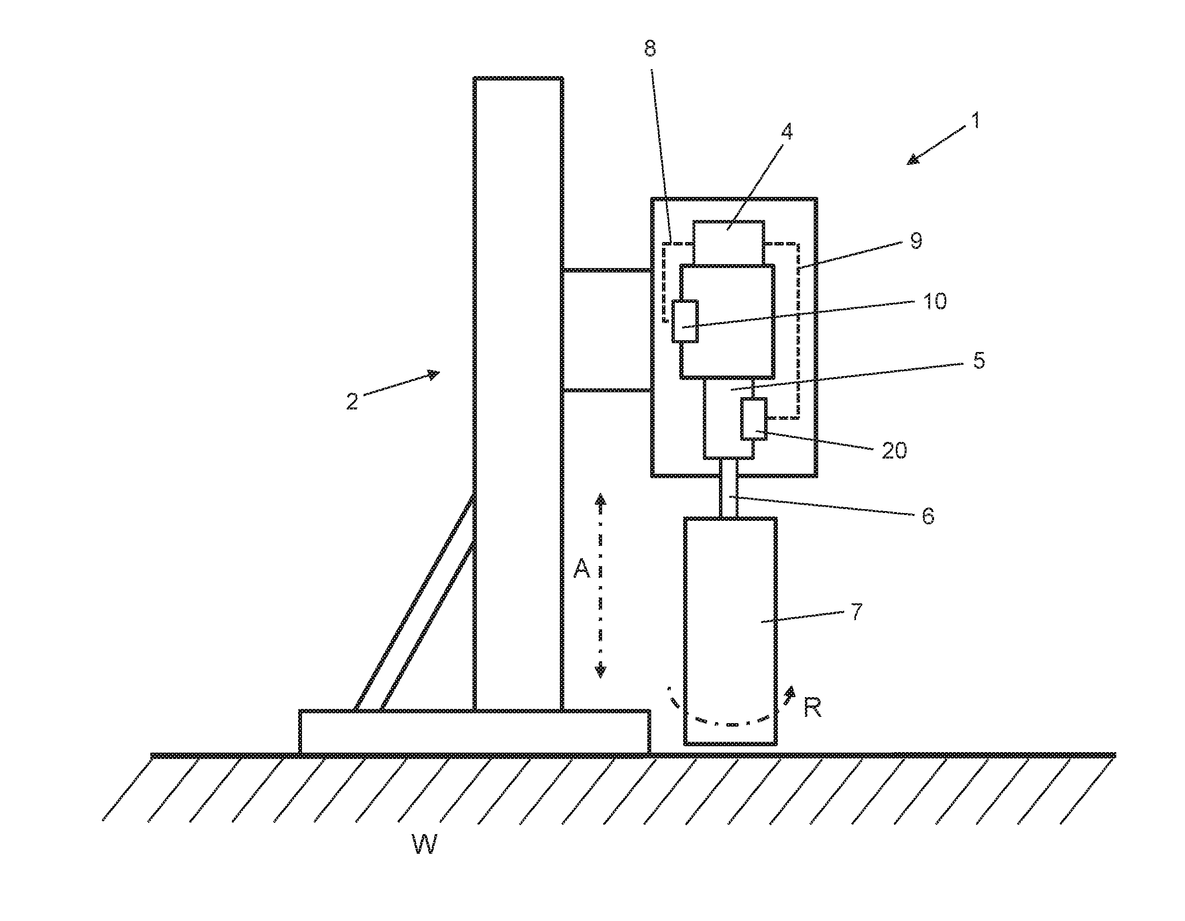
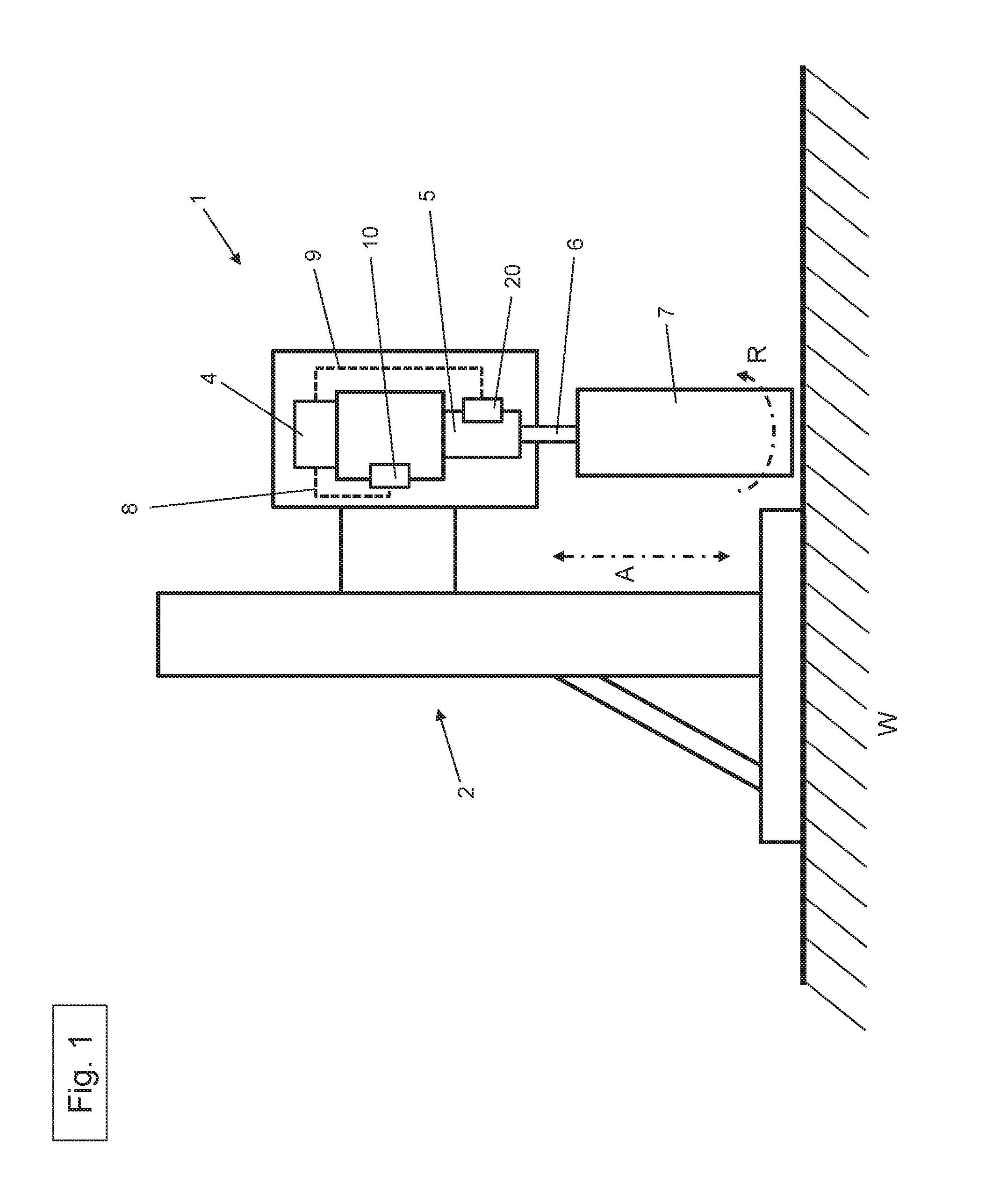
[0037]FIG. 1 shows a power tool 1 configured as a core drill that is attached to a drill stand 2. By means of the drill stand 2, the core drill 1 can be reversibly moved along the double-arrow direction A towards as well as away from the workpiece W that is to be worked. The material W is concrete.

[0038]The core drill 1 has a motor 3, a control unit 4, a transmission 5, a driven shaft 6, a tool 7 configured as a core bit, a first sensor 10 to detect the rotational speed of the transmission 5 and a second sensor 20 to detect the rotational speed of the motor 3. Any type of electric motor can be used as the motor 3.

[0039]The motor 3 is configured as an electric motor and it serves to drive the core bit 7. The motor 3 has a drive shaft that is detachably connected to the transmission 5. This connection is established by a coupling means. The core bit 7 is made to rotate by means of the transmission 5 and the driven shaft 6. The torque generated in the motor 3 is thus correspondingly tr...


PUM

PropertyMeasurementUnit
Speedaaaaaaaaaa

Abstract

A method to control a power tool includes the following steps: ascertaining a first rotational speed of the transmission in a first gear; ascertaining a first rotational speed of the motor when the transmission has been put into a first gear; ascertaining the selection of a first gear on the basis of the ratio of the rotational speed of the transmission and the rotational speed of the motor on the basis of a look-up table; selecting the no-load state; ascertaining the selected no-load state on the basis of the ratio of the rotational speed of the transmission and the rotational speed of the motor on the basis of a look-up table; adapting the rotational speed of the motor to a second gear on the basis of a ratio of the rotational speed of the transmission and the rotational speed of the motor on the basis of a look-up table; and selecting a second gear.

Description

[0001]The present invention relates to a method to control a power tool, especially a core drill, comprising a motor as the drive for the power tool, a control unit, a transmission having at least a first gear, a second gear as well as a no-load state, a tool such as, for instance, a core bit, a first sensor to detect the rotational speed of at least one component of the transmission and a second sensor to detect the rotational speed of the motor.[0002]Moreover, the invention relates to a power tool, especially a core drill, comprising a motor as the drive for the power tool, a control unit, a transmission having at least a first gear, a second gear as well as a no-load state, a tool such as, for instance, a core bit, a first sensor to detect the rotational speed of at least one component of the transmission and a second sensor to detect the rotational speed of the motor, for purposes of using the method according to the invention.BACKGROUND[0003]Power tools such as, for example, co...

Claims


Application Information

Patent Timeline
IPC IPC(8): B25F5/00B28D1/04G05B19/404B23B47/26
CPCB25F5/001B23B47/26B28D1/041G05B19/404G05B2219/41184B23B2270/486B23B2260/07G05B2219/41183B23B2270/32B23B49/00B25B21/008G05B2219/37297Y10T408/165
Inventor SATTLER, CHRISTIAN
Owner HILTI AG
Why Eureka
Try Eureka