

Lens Driving Device and Camera Module Comprising Same
a technology of driving device and lens, which is applied in the direction of camera focusing arrangement, printers, instruments, etc., can solve the problems of deterioration of lens driving device performance, limited ability to detect the position of the lens, and inability to accurately detect so as to prevent deterioration of the linear movement characteristics of the bobbin, accurate detection of the position of the bobbin, and stable maintenance of electromagnetic for
Active Publication Date: 2017-01-19
LG INNOTEK CO LTD
View PDF36 Cites 36 Cited by
- Summary
- Abstract
- Description
- Claims
- Application Information
AI Technical Summary
Benefits of technology
This patent is about a lens driving device and camera module that use a sensing magnet to determine the position of the bobbin (the part that holds the lens) during focus adjustment. The sensing magnet is mounted on the outside of the bobbin, and its position is sensed by a displacement sensing part like a Hall sensor. The position of the lens is readjusted by feedback on the amount of displacement in the optical axis direction, which shortens the time needed for focus alignment and minimizes the distance between the sensing magnet and the displacement sensing part. This improves the accuracy and speed of positioning the lens. The sensing magnet and displacement sensing part are mounted on the same sides, simplifying assembly processes. The position sensor and the bipolar-magnetized magnet are arranged to sense a magnetic field that changes linearly, ensuring accurate sensing of the lens movement. Overall, this technology improves space efficiency and accuracy in the camera module.
Problems solved by technology
However, conventional miniature digital cameras have a problem in that an auto-focusing time taken to perform an auto-focusing function is considerably long.
Therefore, many efforts have been made to shorten the auto-focusing time, but the performance of the lens driving device may be deteriorated somewhat due to the unstable electromagnetic force and eccentricity of a lens barrel attributable to magnetic force.
The position of the lens in the optical axis direction may be detected using the voltage output from the Hall sensor, but the Hall sensor is incapable of accurately sensing the movement of the lens in the optical axis direction, and thus there is a limitation with respect to the ability to detect the position of the lens.
Method used
View moreImage
Smart ImageViewing Examples


Examples
Embodiment Construction
[0353]Various embodiments have been described in the best mode for carrying out the invention.
INDUSTRIAL APPLICABILITY
[0354]A lens driving device and a camera module including the same according to the embodiments are applicable to mobile appliances such as mobile phones (or, portable phone) and smart phones, and are also applicable to various multimedia fields including notebook type personal computers, tablet PCs, camera phones, PDAs, smart phones and toys, and to image input equipment including monitoring cameras and information terminals for video tape recorders.
Login to View More PUM
 Abstract
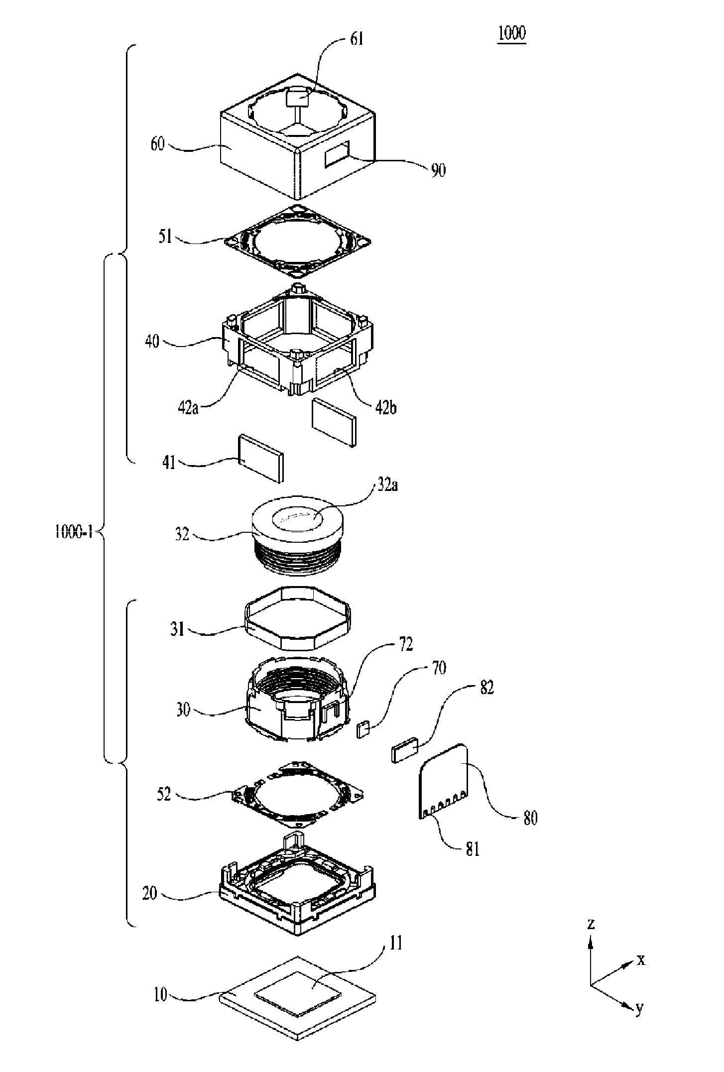
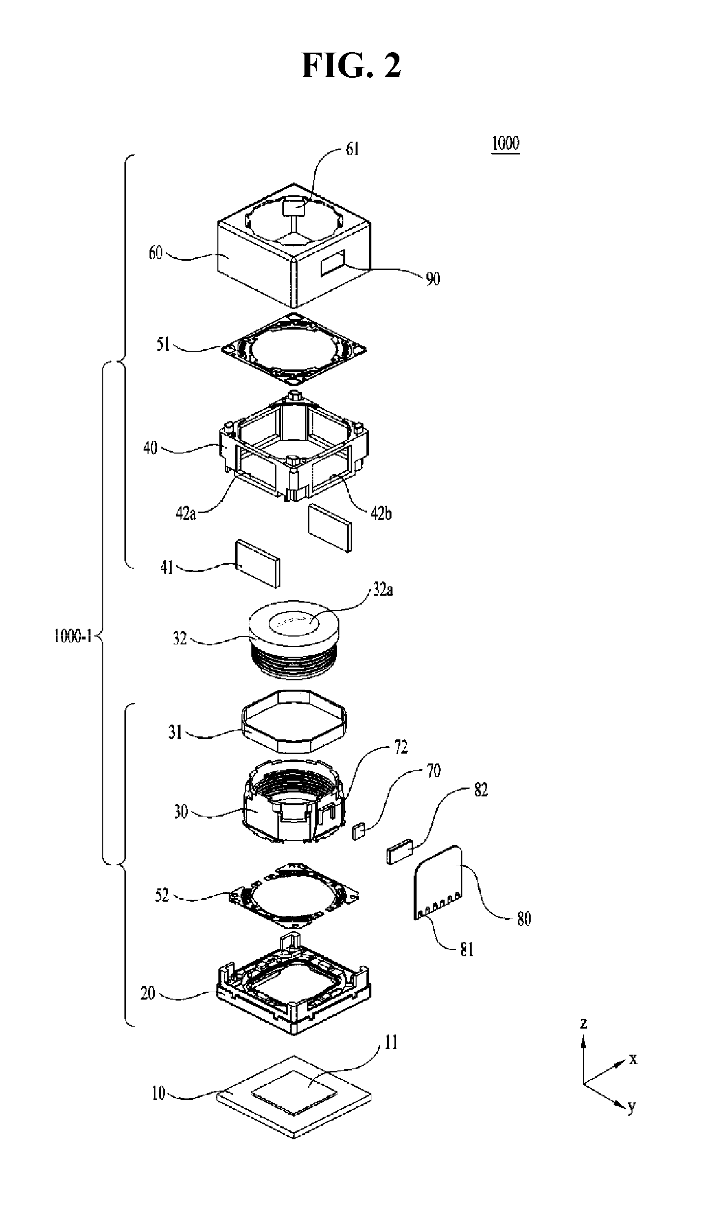
A lens driving device according to an embodiment comprises: a movable unit on which at least one lens is mounted; a first coil and a driving magnet which face and interact with each other such that the movable unit is moved in the optical axis direction of the lens; a position sensor for sensing the position of the movable unit in the optical axis direction or a driver comprising the position sensor; and a positively magnetized magnet arranged to face the position sensor or the driver, wherein the positively magnetized magnet comprises a first side surface, which faces the position sensor and has a first polarity, and a second side surface, which faces the position sensor, which is arranged to be spaced from the first side surface in a direction parallel with the optical axis direction or arranged to abut the first side surface, and which has a second polarity that is the opposite of the first polarity of the first side surface, and the length of the first side surface in the optical axis direction may be equal to or larger than the length of the second side surface in the optical axis direction.
Description
TECHNICAL FIELD[0001]Embodiments relate to a lens driving device and a camera module including the same.BACKGROUND ART[0002]Recently, products in the field of IT having built-in miniature digital cameras, such as mobile phones, smart phones, tablet PCs, laptops, etc., have been actively developed. Camera modules including digital cameras are required to have various functions, such as auto-focusing, alleviation of shutter shake, a zoom function, etc., and the recent trend in the development thereof is focused on increasing pixel count and miniaturization.[0003]Conventional camera modules may include lens driving devices capable of performing an auto-focusing function and a hand shake compensation function. The lens driving devices may be constituted in various fashions, among which a voice coil unit motor is commonly used. The voice coil unit motor is operated by the electromagnetic interaction between a magnet secured to a housing and a coil unit wound around an outer peripheral su...
Claims
Login to View More Application Information
Patent Timeline
 Patent Type & AuthorityApplications(United States)
IPC IPC(8): G02B7/08
CPCG02B7/08G03B3/10H02K41/0356G03B2205/0069
InventorPARK, SANG OKSON, BYUNG WOOKLEE, SEONG MINLEE, JUN TAEK
OwnerLG INNOTEK CO LTD