Multilayer ceramic capacitor

Active Publication Date: 2017-01-19
MURATA MFG CO LTD
View PDF5 Cites 21 Cited by
  • Summary
  • Abstract
  • Description
  • Claims
  • Application Information

AI Technical Summary

Benefits of technology

The present invention provides a reliable multilayer ceramic capacitor that is resistant to moisture and has high thermo-mechanical strength. The second outer electrode layer covers a certain amount of the length of the first outer electrode layer, ensuring a sufficient amount of a Ni-Cu solid solution layer that is necessary for moisture resistance. Ni of the first outer electrode layer is diffused in the second outer electrode layer over a certain distance, ensuring a sufficient Ni diffusion distance to improve moisture resistance.

Problems solved by technology

However, the multilayer ceramic capacitor (multilayer ceramic electronic component) 101, which has the above-described structure, has a problem in that, although the multilayer ceramic capacitor 101 has the interdiffusion layer 120 between the metal layer 119 and the plating 114, the multilayer ceramic capacitor 101 does not always have a sufficient reliability in moisture resistance, depending on the degree of interdiffusion of a Ag—Cu—Ti alloy (metal layer 119) and Cu (plating 114).

Method used


Image

  • Multilayer ceramic capacitor
  • Multilayer ceramic capacitor
  • Multilayer ceramic capacitor

Examples


embodiment 1

Preferred Embodiment 1

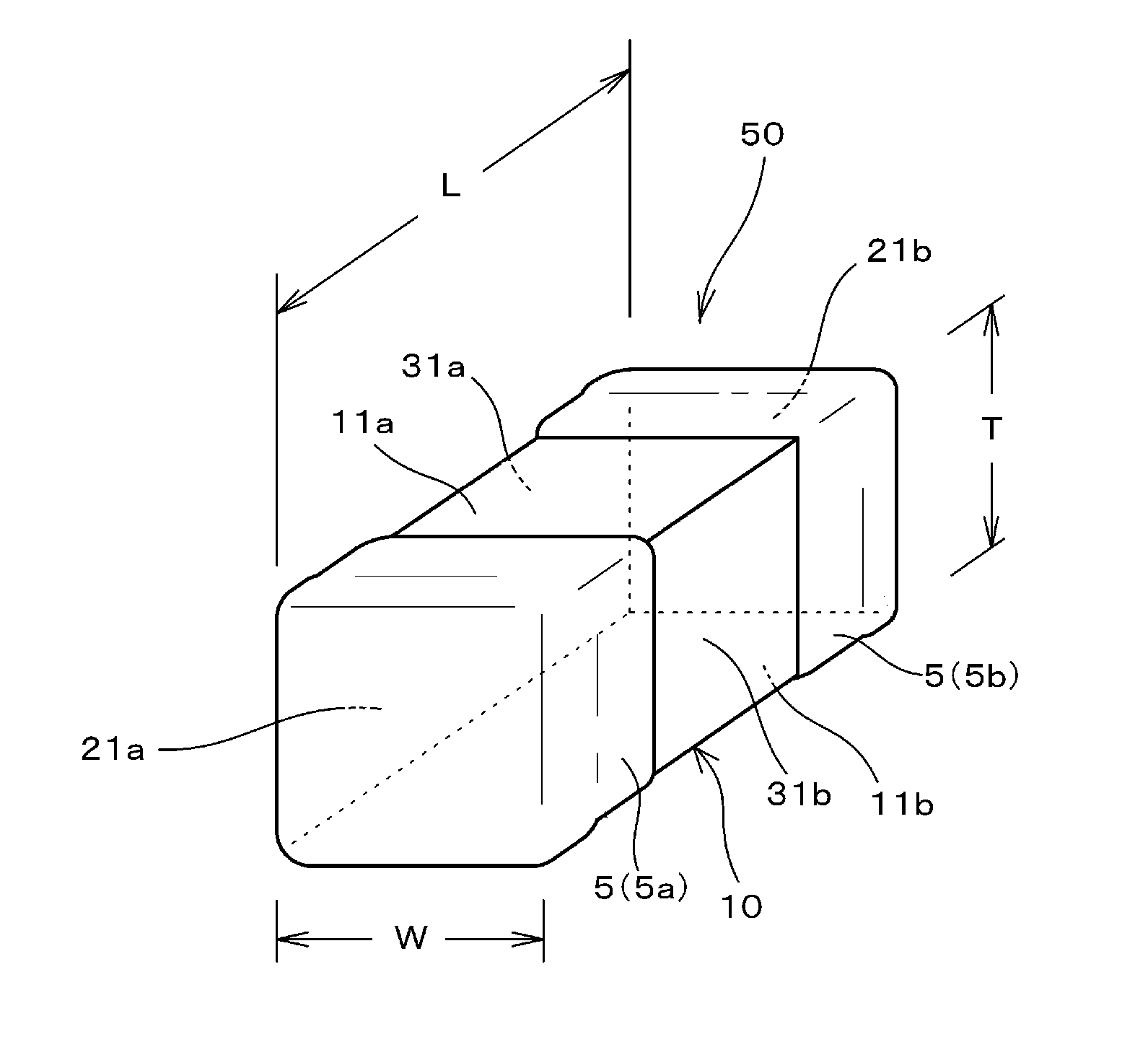
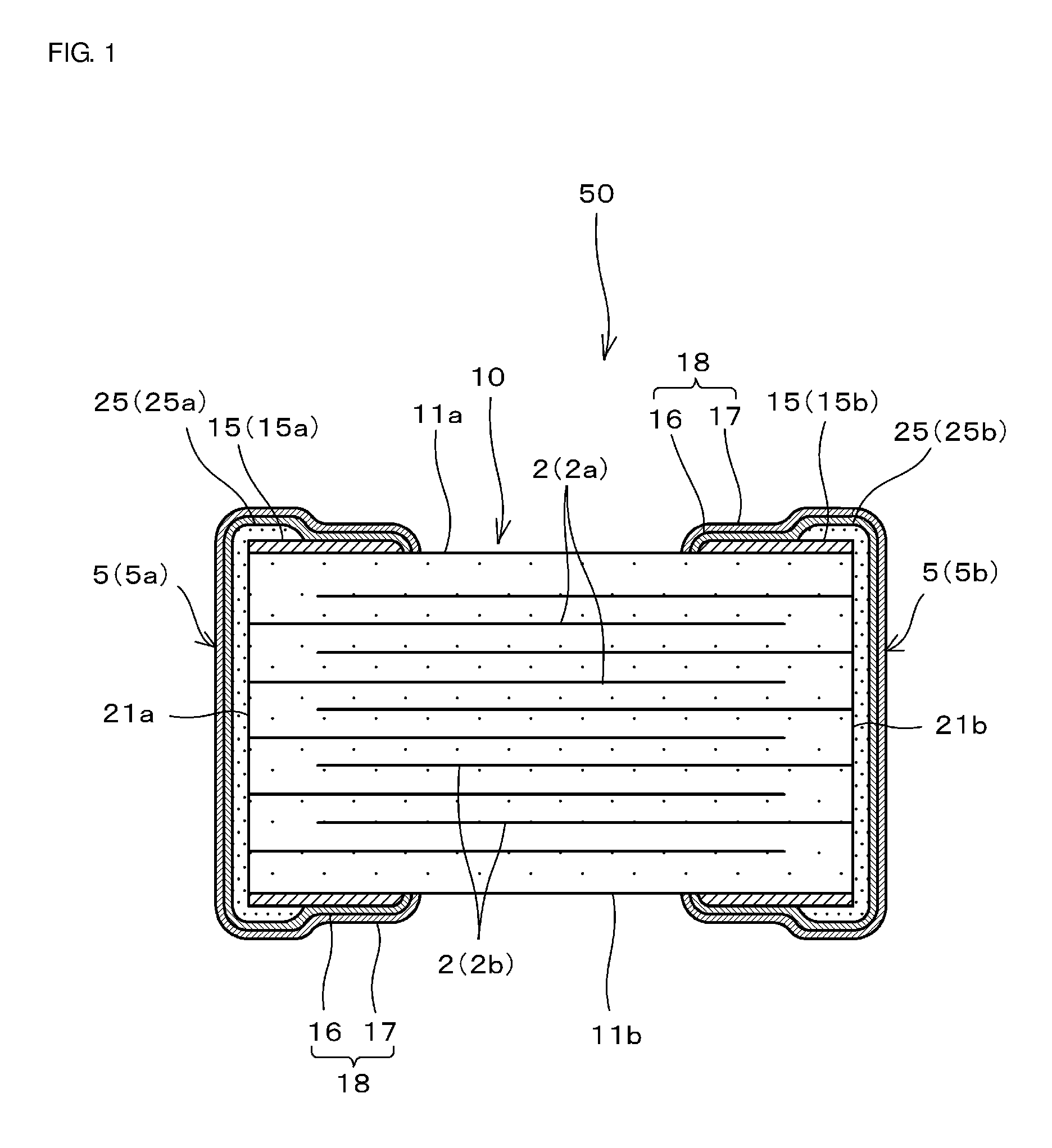
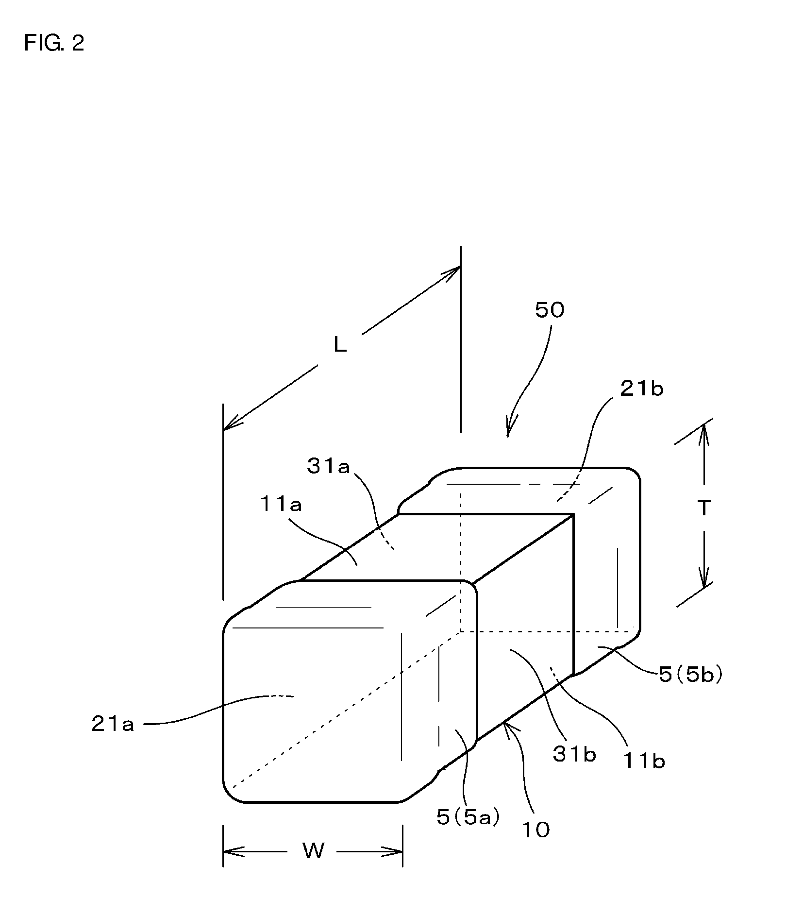
[0026]FIG. 1 is a front cross-sectional view showing a structure of a multilayer ceramic capacitor 50 of one preferred embodiment (Preferred Embodiment 1) of the present invention, and FIG. 2 is a perspective view showing the appearance of the multilayer ceramic capacitor 50.

[0027]As shown in FIGS. 1 and 2, the multilayer ceramic capacitor 50 includes a multilayer body (ceramic base body) 10 including a stack of dielectric layers 1 made of a dielectric ceramic material and inner electrodes 2 (first and second inner electrodes 2a and 2b); and a pair of outer electrodes 5 (5a, 5b) disposed on the outer surface of the multilayer body 10 so as to be in electrical communication with the inner electrodes 2 (2a, 2b). The outer electrodes 5 (5a, 5b) each include a plating 18 on the surface thereof. Each plating 18 includes a two-layer structure including a Ni plating 16 and a Sn plating 17.

[0028]The following more specifically describes each element of the multilayer c...

embodiment 2

Preferred Embodiment 2

[0112]In the present preferred embodiment, samples of Examples 2-1, 2-2, 2-3, 2-4 and 2-5 and samples of Comparative Examples 4 and 5 were prepared. In each of these samples, the length D1 (see FIG. 3) in the L direction of a portion of the second outer electrode layer 25 (25a, 25b) which overlies the first outer electrode layer 15 (15a, 15b) is as shown in Table 2. The length in the L direction of the first outer electrode layer 15 (15a, 15b) is defined as E (see FIG. 3).

[0113]These samples were subjected to the humidity loading test and the IR failure rate was determined. The humidity loading test was performed in the same manner under the same conditions as in Preferred Embodiment 1.

[0114]In addition, a thermal shock cycling test was performed in the following manner and cracking rate of Examples and Comparative Examples was determined.

[0115]Before the thermal shock cycling test, first, each sample was soldered to a board under the following conditions.

[0116...

embodiment 3

Preferred Embodiment 3

[0134]Samples of Examples 3-1, 3-2, 3-3, and 3-4 and a sample of Comparative Example 6, in which the diffusion distance D2 differs from sample to sample, were prepared in the same manner as in Preferred Embodiment 1. The diffusion distance D2 is a distance over which Ni of the first outer electrode layer is diffused in a portion of the Cu-containing second outer electrode layer which overlies the first outer electrode layer (see FIGS. 4A and 4B).

[0135]The diffusion distance D2, over which Ni of the first outer electrode layer is diffused in the second outer electrode layer containing Cu, was changed by changing the baking temperature of the second outer electrode layer within the range of about 300° C. to about 700° C., for example.

[0136]FIG. 4A is a cross-sectional view schematically showing structures of the first and second outer electrode layers 15 and 25 of a multilayer ceramic capacitor of Preferred Embodiment 3, and FIG. 4B is an enlarged view of area A ...


PUM

PropertyMeasurementUnit
Fractionaaaaaaaaaa
Fractionaaaaaaaaaa
Fractionaaaaaaaaaa

Abstract

In a multilayer ceramic capacitor, each outer electrode includes a first outer electrode layer that contains Ni and that is disposed on each main surface of a multilayer body and a second outer electrode layer that contains a glass component and Cu and that covers one end portion of the first outer electrode layer which is closer to an end surface of the multilayer body, the first and second outer electrode layers are joined together in a region including an edge shared by the main surface and the end surface, the other end portion of the first outer electrode layer is exposed from the second outer electrode layer, and Ni of the first outer electrode layer is diffused in the second outer electrode layer and is dissolved in Cu of the second outer electrode layer to define a solid solution in the region including the edge.

Description

CROSS REFERENCE TO RELATED APPLICATIONS[0001]This application claims the benefit of priority to Japanese Patent Application 2016-0099537 filed May 18, 2016 and Japanese Patent Application 2015-140603 filed Jul. 14, 2015. The entire content of each application are hereby incorporated by reference.BACKGROUND OF THE INVENTION[0002]1. Field of the Invention[0003]The present invention relates to a ceramic capacitor. Specifically, the present invention relates to a multilayer ceramic capacitor that includes a multilayer body including a stack of inner electrodes and dielectric layers, and outer electrodes disposed on the surface of the multilayer body so as to be connected to the inner electrodes.[0004]2. Description of the Related Art[0005]In recent years, multilayer ceramic capacitors including a multilayer body constituted by a stack of inner electrodes and dielectric layers, and outer electrodes disposed on the surface of the multilayer body so as to be connected to the inner electrod...

Claims


Application Information

Patent Timeline
IPC IPC(8): H01G4/30H01G4/12H01G4/008H01G4/248
CPCH01G4/30H01G4/008H01G4/12H01G4/248H01G4/2325H01G4/232
Inventor NISHISAKA, YASUHIRO
Owner MURATA MFG CO LTD
Why Eureka
Try Eureka