Energy efficient refrigeration system

a refrigeration system and energy-saving technology, applied in the field of efficient refrigeration systems, can solve the problems of condensate remaining in the pan, and achieve the effect of shortening the time it takes

Active Publication Date: 2017-01-26
KILLION IND INC
View PDF28 Cites 6 Cited by
  • Summary
  • Abstract
  • Description
  • Claims
  • Application Information

AI Technical Summary

Benefits of technology

[0008]A condensate collection pan made sufficiently large enough to hold all of the condensate expected to be generated during operation of the refrigeration system at any given time is designed to accommodate an electric heating element, a hot gas loop, coil, or other configuration of hot gas tubing from the refrigeration system employed, and a limit switch controlled by a liquid level float or other liquid level sensing switch that turns the heating element on and off. Further, the refrigeration system defrost timer is wired so that when the condensing unit is turned off for the defrost cycle the heating element is turned on for the duration of the defrost cycle. In addition to this, the temperature controller that regulates the on-off durations of the condensing unit during the cooling cycle is also wired so that when the condensing unit is turned off for case temperature regulation, the heating element is simultaneously turned on for the same duration. In certain embodiments, the condensing unit fan is wired to continuously run so that steam generated from boiling off the condensate is removed from the refrigerator's interior. Because the high electrical current draw of the compressor is alternating with the high electrical current draw of the heating element, no additional electrical service is required for the heating element. In other embodiments, the hot gas loop from the refrigeration system is used to preheat the condensate to assist the electric heating element in order to shorten the amount of time it takes to heat the condensate to point of evaporation.

Problems solved by technology

The time it takes for the water to be raised from room temperature to the point of evaporation is too long resulting in condensate remaining in the pan after the defrost cycle has ended.

Method used


Image

  • Energy efficient refrigeration system
  • Energy efficient refrigeration system
  • Energy efficient refrigeration system

Examples


Embodiment Construction

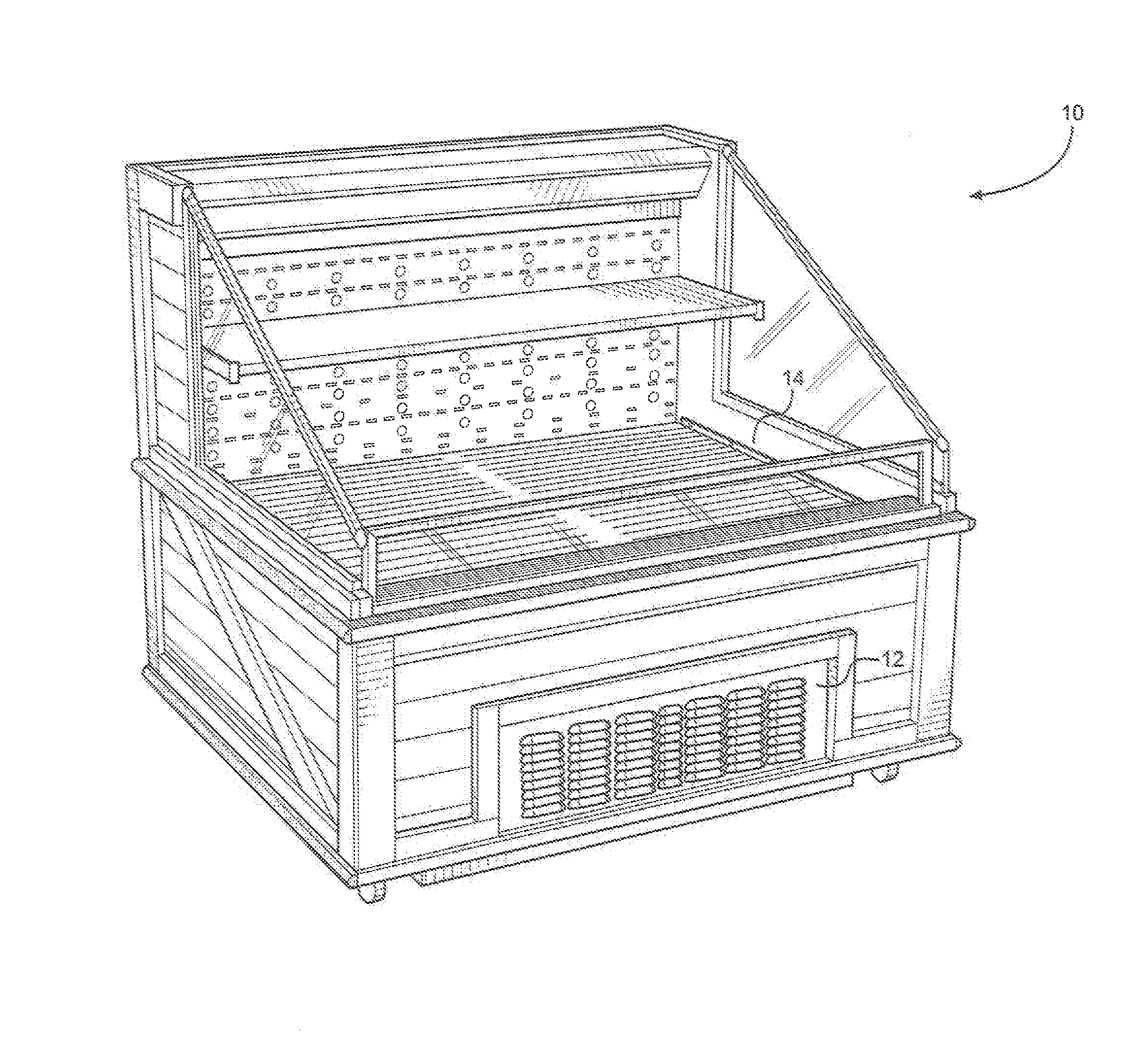
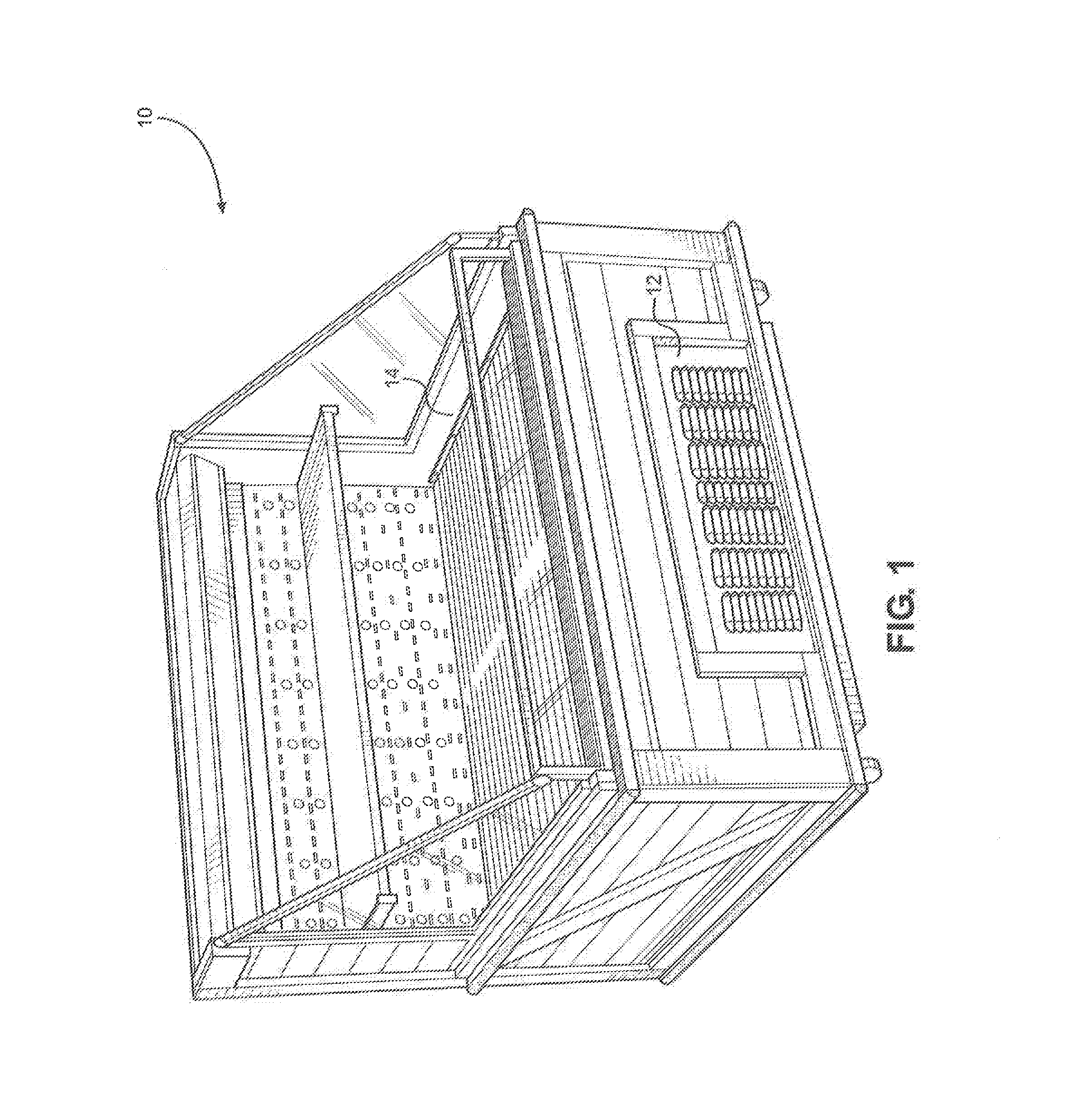
[0028]Referring initially to FIG. 1, a perspective view of the front of a portable and self-contained refrigerated display case is shown and referred to as 10. Refrigerated case 10 has a refrigerated space 14 that is cooled by the refrigeration system 20 (not shown, see FIG. 2) Located on the front of the refrigerated case 10 is air inlet cover 12 that allows cool air to enter the interior of the refrigerated case 10 to cool the refrigeration system 20. Air inlet cover 12 may also consist of air filters to prevent dirt and dust from entering the interior of refrigerated case 10, which may reduce air flow through the system thereby reducing efficiency and increasing total power usage.

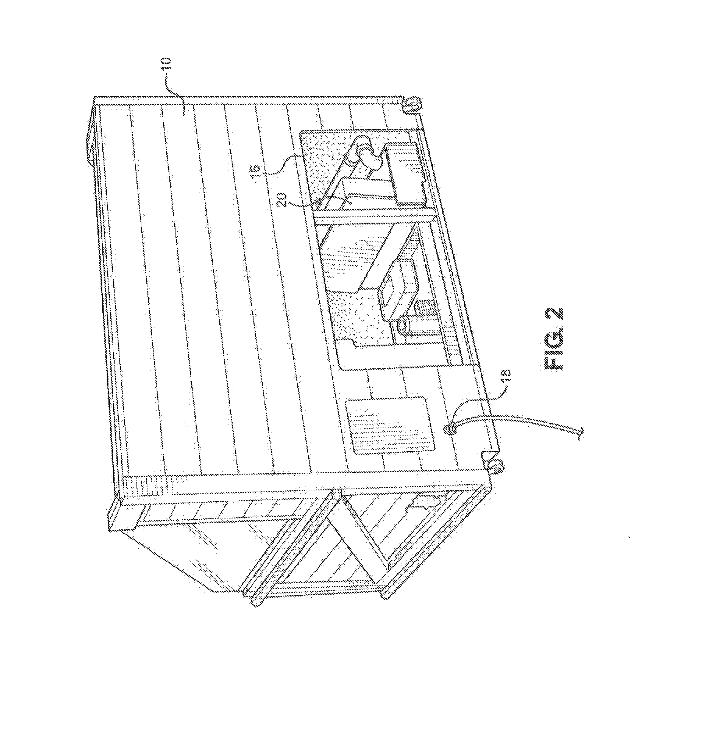
[0029]Referring now to FIG. 2, a perspective view of the rear of refrigerated case 10 is shown. Located at the rear of refrigerated case 10 are power cord 18, air outlet 16, and refrigeration system 20. Power cord 18 may be configured to connect to various power systems, such as systems that supply power...


PUM


Abstract

A preferred embodiment utilizes the waste heat from a refrigerant cycle to aid in the removal of condensate from a refrigerated case used primarily by grocery stores. Certain embodiments use a heating element to boil off condensate or a pump to remove the condensate. Another embodiment utilizes a wicking element and a shroud that directs hot air from the condenser through the wick thereby increasing the condensate evaporation rate. Yet another embodiment utilizes the hot gas tube from the refrigeration system routed through the bottom of the condensate tray to pre-heat the condensate to accelerate evaporation. Alternative embodiments combine certain features to create even more efficient system such as a heating element used with the wick system or the hot gas system used with the wick system. In some embodiments, a mold and mildew inhibitor is added to the condensate to maintain cleanliness.

Description

RELATED APPLICATIONS[0001]The application claims the benefit of priority to U.S. Provisional Patent Application Ser. No. 62 / 127,400 entitled “Energy Efficient Refrigeration System”, filed on Mar. 3, 2015, and currently co-pending.FIELD OF THE INVENTION[0002]The present invention pertains generally to efficient refrigeration systems for use in grocery stores and cold food storage. More particularly, the present invention pertains to an efficient method of removing condensate that collects during operation by utilizing waste heat and airflow generated by the refrigeration system. The Present invention is particularly, but not exclusively, useful as a way to reduce energy consumption of portable or self-contained refrigeration units.BACKGROUND OF THE INVENTION[0003]Supermarket departments are typically designed and setup with remote refrigeration systems where remote refrigerated cases such as wall units and islands are installed with and controlled by central compressor banks / condensi...

Claims


Application Information

Patent Timeline
Patent Type & Authority Applications(United States)
IPC IPC(8): A47F3/04
CPCA47F3/0478A47F3/0469A47F3/0443A47F3/0482F25D21/14F25D2321/1412F25D2321/1413
Inventor FISCHER, KARL
Owner KILLION IND INC
Why Eureka
Try Eureka