Method and magnetic resonance apparatus for quality control in planning radiotherapy of a patient

a quality control and patient technology, applied in the field of quality control in the planning of radiotherapy of a patient, can solve the problems of new challenges in mr-only rt planning, and achieve the effect of reducing the absorption of photons and reducing the electron density

Active Publication Date: 2017-01-26
SIEMENS HEALTHCARE GMBH
View PDF3 Cites 7 Cited by
  • Summary
  • Abstract
  • Description
  • Claims
  • Application Information

AI Technical Summary

Benefits of technology

[0032]In this way the described procedure thus supplies a quality indicator for the dose-calculation that is produced on the basis of magnetic resonance image data only. The described procedure thus makes a decision easier for a user between conventional radiotherapy planning using CT image data and MR-only RT planning. The described procedure provides an indicator of the robustness of radiotherapy planning on solely synthetic CT image data. The described steps can proceed completely automatically, or semi-automatically. A subjective decision, based on qualitative experiences of radio-oncologists can be underpinned by the inventive procedure by quantitative values whose calculation requires only low user effort. Low quality radiotherapy treatments due to MR-only RT planning can be ruled out. At the same time the quality level of the radiotherapy treatments can be increased by identification of the patients suitable for magnetic resonance-based and CT-based planning.
[0038]In another embodiment, the reduction in the second value of the electron density in the second electron density map compared to the first value of the electron density in the first electron density map is accomplished by the second value of the electron density in the at least one bone region being set to a value of an electron density of soft tissue. In particular, the electron density value can be set to the value of the electron density of soft tissue when ascertaining the second electron density map for all pixels or voxels in the at least one bone region. In this way, the at least one bone region can no longer be distinguished from the surrounding soft tissue regions in the second electron density map. The second electron density map therefore can be filled by continuous soft tissue occupancy. Examples of soft tissue are muscle tissue, water tissue, fat tissue, etc. Soft tissue typically has a lower electron density and therefore a lower absorption of photons than bone tissue. By means of the inventive procedure, the effect of the presence of the at least one bone region on radiotherapy planning can be determined particularly easily in this way when comparing the first dose distribution with the second dose distribution.
[0040]In another embodiment, increasing the fourth value of the electron density in the second electron density map compared to the third value of the electron density in the first electron density map is accomplished by setting the fourth value of the electron density in the at least one air region to a value of an electron density of soft tissue. In this way the at least one air region in the second electron density map can be occupied analogously to the at least one bone region with the electron density of soft tissue. A particularly homogeneous second electron density map can be obtained thereby.
[0042]In another embodiment, the radiotherapy plan, which is used for ascertaining the first dose distribution of the second dose distribution, is a standard radiotherapy plan that includes typical settings of a radiotherapy system. Such a standard radiotherapy plan can comprise typical radiotherapy settings used in a clinical application for the type of target region. Use of the standard radiotherapy plan can be sufficient in many cases for identifying the effect of the at least one bone region on an applied radiation dose even if the standard radiotherapy plan is not typically matched to the patient. Use of the standard radiotherapy plan can have the advantage that there is still no need for a radiotherapy plan individually adapted to the patient for checking the validity of the first electron density map. In this way a particularly straightforward workflow can be enabled by the use of the standard radiotherapy plan.
[0049]The invention also encompasses a non-transitory, computer-readable data storage medium that can be loaded directly into a memory of a programmable processor of the radiotherapy planning computer. The storage medium is encoded with program code (programming instructions) that causes the inventive method to be implemented when the program code executed in the radiotherapy planning computer. The inventive method can consequently be carried out quickly, robustly and in a manner that can be identically repeated. The computer or the processor thereof must have an appropriate main memory, an appropriate graphics card or an appropriate logic unit, so the method steps can be carried out efficiently.

Problems solved by technology

MR-only RT planning, however, poses new challenges.

Method used


Image

  • Method and magnetic resonance apparatus for quality control in planning radiotherapy of a patient
  • Method and magnetic resonance apparatus for quality control in planning radiotherapy of a patient
  • Method and magnetic resonance apparatus for quality control in planning radiotherapy of a patient

Examples


first embodiment

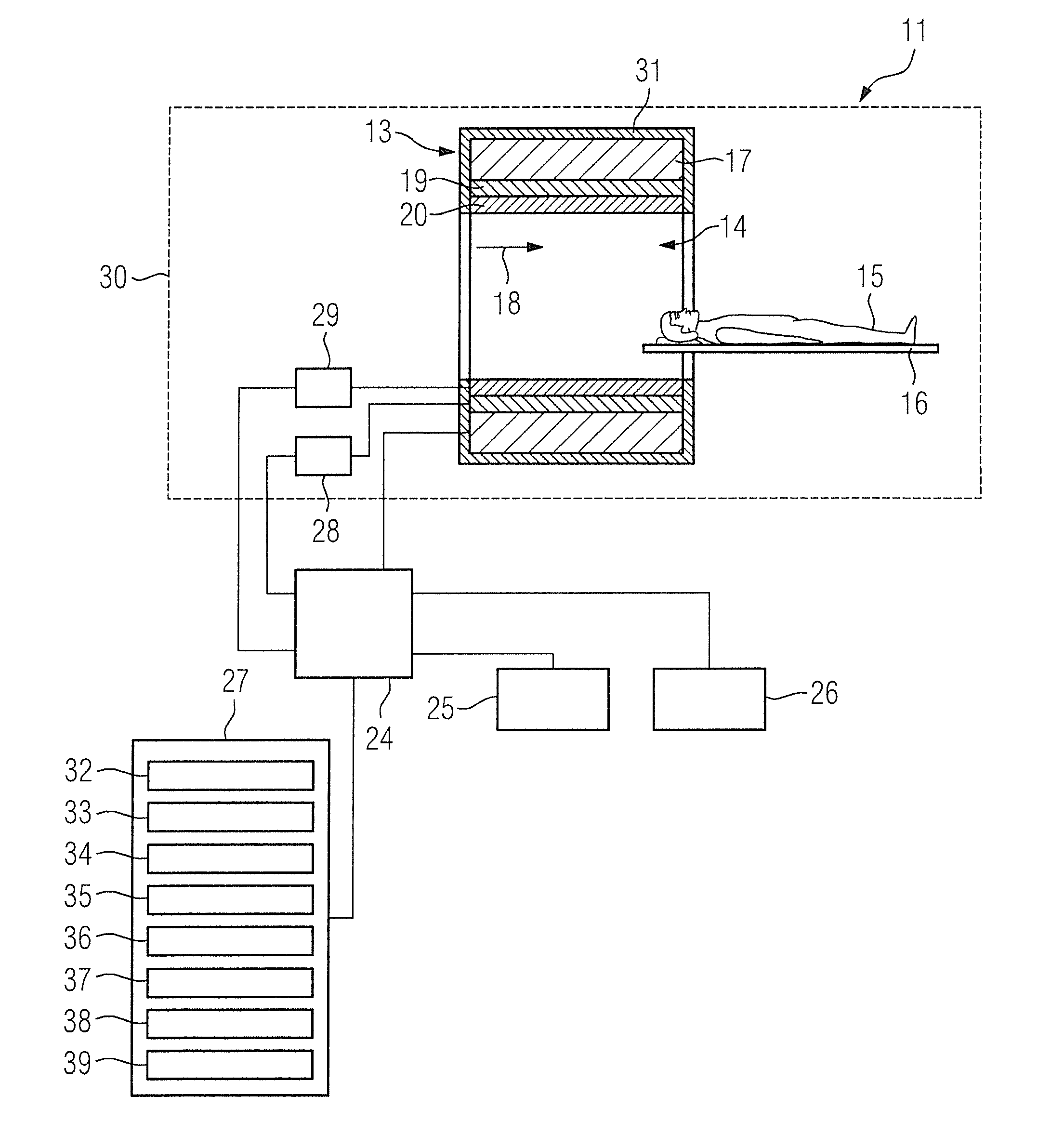
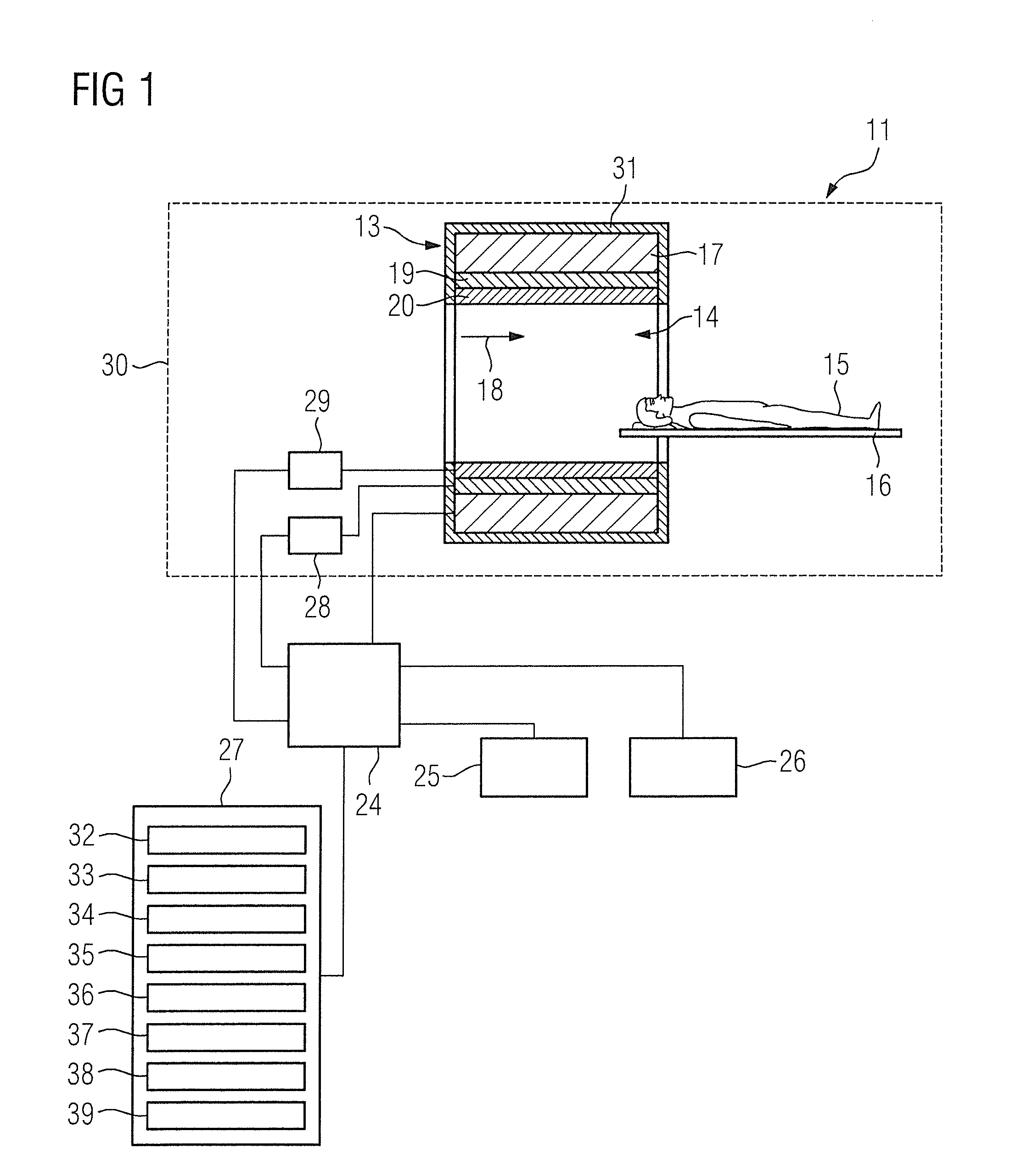
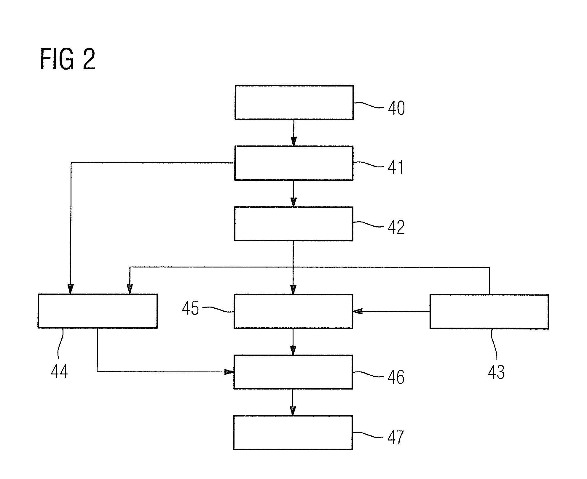
[0061]FIG. 2 shows a flowchart of an inventive method of quality control for planning radiotherapy of a patient 15.

[0062]In a first method step 40 magnetic resonance image data of the patient 15 is acquired from a planning volume by means of the acquisition unit 32.

[0063]In a further method step 41 a first electron density map of the planning volume is ascertained using the magnetic resonance image data by means of the first ascertaining unit 33.

[0064]In a further method step 42 a second electron density map is calculated using the first electron density map by means of the calculation unit 34, wherein there is a reduction in a second value of the electron density in the second electron density map compared to a first value of the electron density in the first electron density map for at least one bone region in the planning volume.

[0065]In a further method step 43 a radiotherapy plan for radiotherapy of a target volume is supplied, which volume is localized in the planning volume, ...

second embodiment

[0070]FIG. 3 shows a flowchart of an inventive method of quality control for planning radiotherapy of a patient 15.

[0071]The following description is essentially limited to the differences from the exemplary embodiment in FIG. 2, with reference being made with respect to unchanging method steps to the description of the exemplary embodiment in FIG. 2. Method steps that are essentially unchanged are basically numbered with the same reference numerals.

[0072]The embodiment of the inventive method shown in FIG. 3 essentially comprises the method steps 40, 41, 42, 43, 44, 45, 46, 47 of the first embodiment of the inventive method according to FIG. 2. In addition, the embodiment of the inventive method shown in FIG. 3 has additional method steps and sub-steps. A method sequence alternative to FIG. 3 is also conceivable which has only some of the additional method steps and / or sub-steps illustrated in FIG. 3. Of course a method sequence alternative to FIG. 3 can also have additional method...


PUM


Abstract

In a quality control method and computer for planning radiotherapy of patient, magnetic resonance (MR) image data, acquired from a planning volume of a patient, are provided to a computer and are used in the computer to generate a first electron density map of the planning volume. A second electron density map is generated using the first electron density map, wherein a value of electron density for a bone region in the planning volume is reduced compared to the first electron density map. First and second radiation dose distributions in the planning volume are respectively determined from the radiotherapy plan and the first electron density map, and the radiotherapy plan and the second electron density map. These distributions are compared in order to generate output information.

Description

BACKGROUND OF THE INVENTION[0001]Field of the Invention[0002]The invention concerns a method for quality control in planning radiotherapy of a patient, as well as a radiotherapy planning computer, a magnetic resonance apparatus and a non-transitory, computer-readable data storage medium for implementing such a method.[0003]Description of the Prior Art[0004]With radiation therapy, target tissue, such as a tumor, of a patient is irradiated with ionizing radiation. External radiation therapy, in which radiotherapy of the body of the patient is implemented from a radiation source outside of the body, is known for use in this context. Internal radiation therapy, also called brachytherapy, is also known. With brachytherapy, radiation sources, composed of radioactive substances, are introduced into the body of the patient to locally damage or destroy target tissue in the body of the patient.[0005]It is known to plan and / or monitor radiation therapy of a patient by the use of imaging. For t...

Claims


Application Information

Patent Timeline
Patent Type & Authority Applications(United States)
IPC IPC(8): A61N5/10G06T7/60G06T7/00G01R33/48G01R33/56
CPCA61N5/1039G01R33/4828G01R33/5608G06T2207/30008G06T7/602G06T2207/10088G06T7/0012G01R33/4808
Inventor SCHWEIZER, BERND
Owner SIEMENS HEALTHCARE GMBH
Why Eureka
Try Eureka