
Method for manufacturing ceiling fan blade

a ceiling fan and manufacturing method technology, applied in the direction of machines/engines, mechanical equipment, liquid fuel engines, etc., can solve the problems of heavy wooden fan blades falling to hurt people, difficult installation of conventional ceiling fans, and high loading of motors to rotate ceiling fans, etc., to achieve easy manufacturing and light weight

Inactive Publication Date: 2017-01-26
CHUN WEI CHIANG
View PDF1 Cites 4 Cited by
  • Summary
  • Abstract
  • Description
  • Claims
  • Application Information

AI Technical Summary

Benefits of technology

The invention is about a ceiling fan blade that is easy to make, cheap and light. It is made from a lightweight material called polystyrene foam, which helps reduce the weight of the blade and the strain on the motor. The blade looks similar to traditional ones, but uses less wood. Overall, the technical effect of this invention is to create a lighter, more efficient fan blade that is easier to manufacture and install.

Problems solved by technology

A fan blade made by wooden veneer is weighted approximately 300-350 g, and a fan blade made by wooden fiberboard is weighted approximately 350-400 g. Thus, a conventional ceiling fan including five fan blades may be weighted approximately 1500-2000 g. As a result, a conventional ceiling fan is difficult to install, and the loading of motor to rotate the ceiling fan is quite high.
In addition, when an earthquake or other accident occurs, the heavy wooden fan blade may fall to hurt people.
Besides, the wooden fan blade may accelerate deforestation.
However, the process to manufacture is complicated and time-consuming, and the weight is not really reduced due to the steel bar.
Thus, error of the position of the steel bar may result that the ceiling fan blade lose its balance, and calibration may be necessary during installation.

Method used


Image

  • Method for manufacturing ceiling fan blade
  • Method for manufacturing ceiling fan blade
  • Method for manufacturing ceiling fan blade

Examples


Embodiment Construction

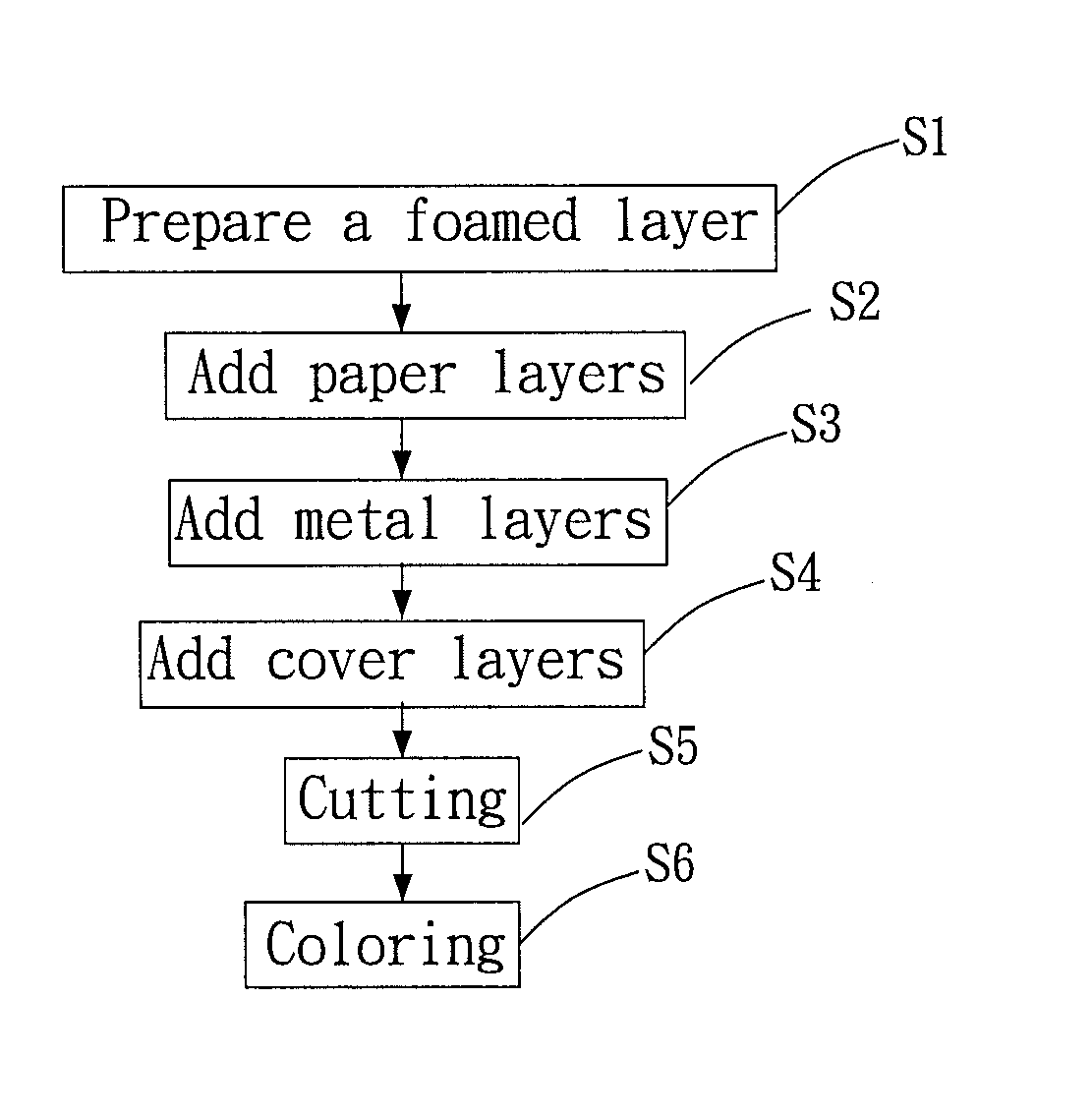
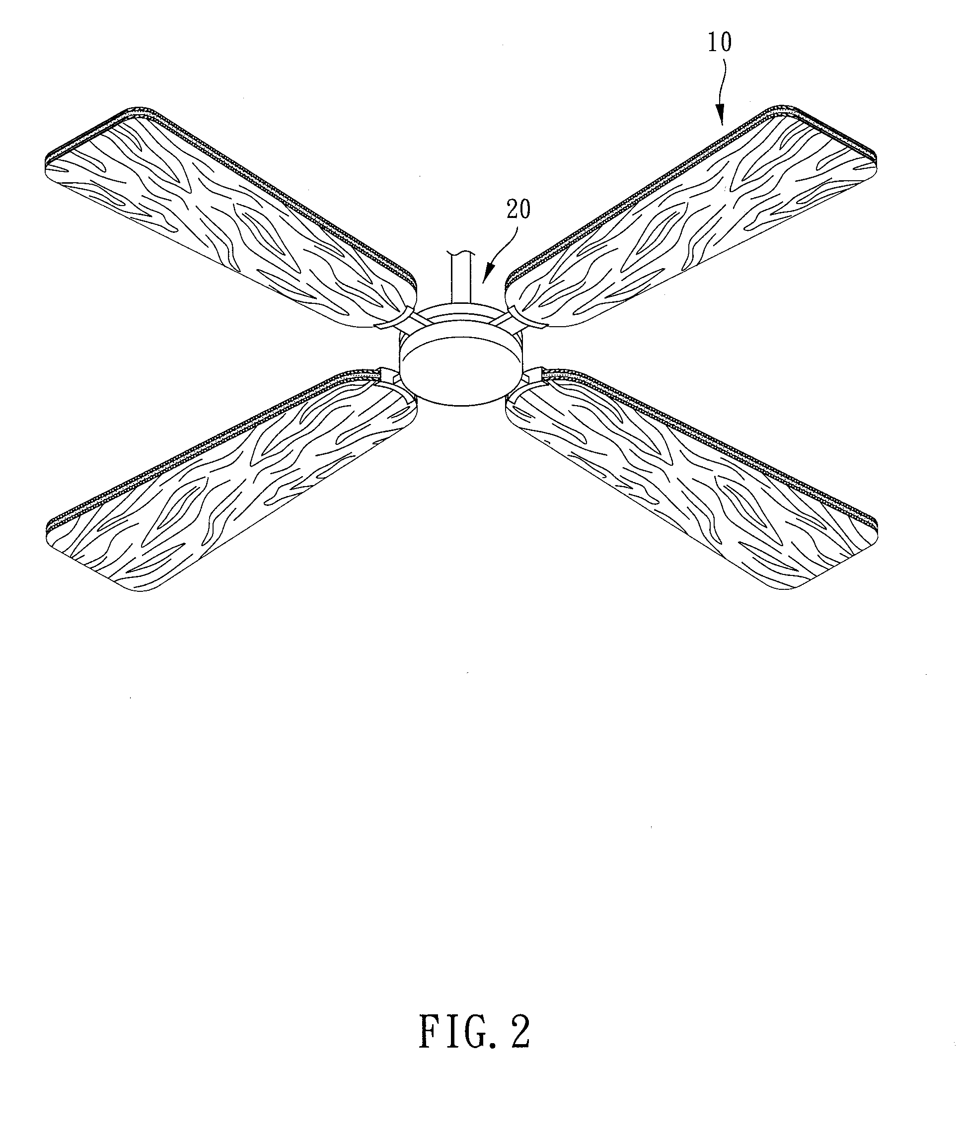
[0020]Please refer to FIG. 1 to FIG. 5 and FIG. 3A, the method for manufacturing ceiling fan blade is provided in the present embodiment. The ceiling fan blade 10, 10′ is adapted for being disposed on a ceiling fan base 20. The method for manufacturing the ceiling fan blade 10, 10′ includes the following steps.

[0021](a) Prepare a foamed layer S1: prepare a polystyrene material and foam the polystyrene material to form a foamed layer 11 which has a predetermined thickness. The foaming magnification of the foamed layer is not larger than 20 to maintain sufficient structure strength.

[0022](b) Add paper layers S2: Position a corrugated paper sheet on each of two opposite faces of the foamed layer 11 to form a paper layer 12 wherein the corrugated paper sheet forms a plurality of passages parallel arranged. More specifically, two paper sheets are adhered onto two opposite faces of the foamed layer 11 from two ends of the thickness direction of the foamed layer by glue or adhesive. The pa...


PUM

PropertyMeasurementUnit
weightaaaaaaaaaa
gravityaaaaaaaaaa
thicknessaaaaaaaaaa

Abstract

A ceiling fan blade includes a foamed layer, two paper layers, and two cover layers. The foamed layer is formed by foaming a polystyrene material. The paper layers are positioned on two opposite faces of the foamed layer respectively The cover layers are positioned on the paper layers respectively so that each paper layer is sandwiched between the foamed layer and one of the cover layers. Thereby, the ceiling fan blade of the present invention is light-weight, low-cost, and easy to manufacture. In addition, energy to rotate the ceiling fan is reduced.

Description

BACKGROUND OF THE INVENTION[0001]Field of the Invention[0002]The present invention is a CIP of application Ser. No. 14 / 168580, filed Jan. 30, 2014, the entire contents of which are hereby incorporated by reference.[0003]Description of the Prior Art[0004]A conventional ceiling fan blade is usually made by wooden veneer or wooden fiberboard. A fan blade made by wooden veneer is weighted approximately 300-350 g, and a fan blade made by wooden fiberboard is weighted approximately 350-400 g. Thus, a conventional ceiling fan including five fan blades may be weighted approximately 1500-2000 g. As a result, a conventional ceiling fan is difficult to install, and the loading of motor to rotate the ceiling fan is quite high.[0005]In addition, when an earthquake or other accident occurs, the heavy wooden fan blade may fall to hurt people.[0006]Besides, the wooden fan blade may accelerate deforestation.[0007]Thus, foam material is introduced to manufacture improved fan blades, as disclosed in p...

Claims


Application Information

Patent Timeline
Patent Type & Authority Applications(United States)
IPC IPC(8): B23P15/04F04D29/38F04D29/64F04D25/08
CPCB23P15/04F04D29/644F04D29/388F04D25/088F05D2300/43F04D29/023F05D2300/612Y10T29/49327F01D5/28F01D5/147F01D5/282
Inventor CHIANG, CHUN-WEIGAU, MING-TSUNG
Owner CHUN WEI CHIANG
Learn More