Radiation Source Assembly

a radiation source and assembly technology, applied in the direction of electric discharge lamps, electrical equipment, water/sludge/sewage treatment, etc., can solve the problems of human harm, risk of quartz sleeves breaking, and prior art focus not on safe disconnection of power from lamps, so as to facilitate closer packing of radiation source assemblies and small construction footprints

Active Publication Date: 2017-01-26
TROJAN TECH
View PDF0 Cites 3 Cited by
  • Summary
  • Abstract
  • Description
  • Claims
  • Application Information

AI Technical Summary

Benefits of technology

[0025]It is another object of the present invention to provide a novel coupling for securing a radiation source assembly to a fluid treatment system.
[0039]Unlike the bayonet arrangement described above with respect to Moglan, the present coupling and radiation source assembly operates on the basis that the lamp plug element can be disengaged from the sleeve bolt element without the need for any rotation of the lamp plug element. This avoids the requirement for additional structure to create the electrical connection between the lamp plug element and the electrical connectors on the elongate radiation source. This also results in a smaller footprint for construction which facilitates closer packing of radiation source assemblies in the fluid treatment system. These are distinct advantages of the present coupling and radiation source assembly.

Problems solved by technology

As is known in the art, a significant amount of electrical power is used to operate the lamps in the fluid treatment systems referred to above and it is known those lamps emit large amounts of ultraviolet radiation which is harmful to humans.
Historically, the prior art has not been focused on safe disconnection of power from the lamp during servicing thereof Thus, for example, it has been common practise to remove the lamp from the fluid treatment system while it is still connected to the power supply and thereafter to disconnect the power supply from the lamp.
There is always a risk of breakage of the quartz sleeve.
If service personnel attempt to remove the lamp and lamp plug from the lamp sleeve, there is a risk that water, together with sleeve and lamp remnants, may be forcibly ejected out of the housing / chamber without warning.
This presents a serious injury risk to service personnel.

Method used


Image

  • Radiation Source Assembly
  • Radiation Source Assembly
  • Radiation Source Assembly

Examples


Embodiment Construction

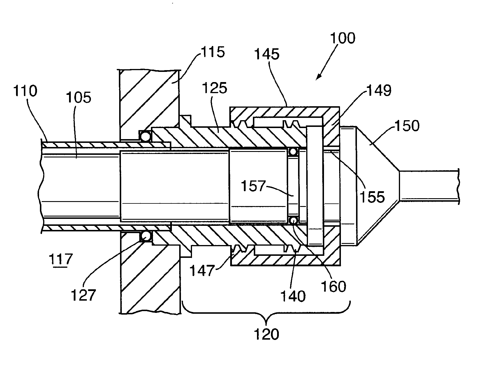
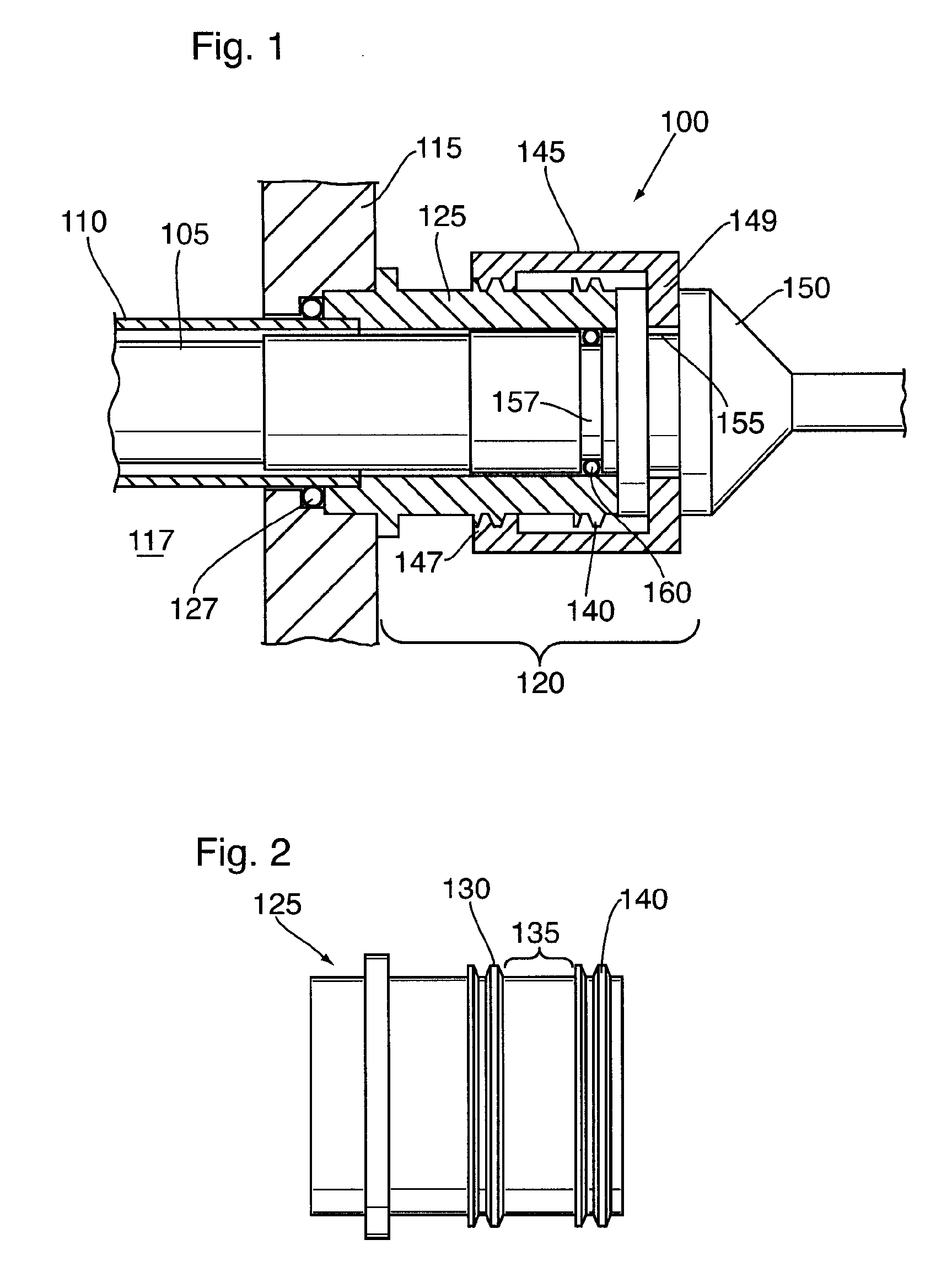
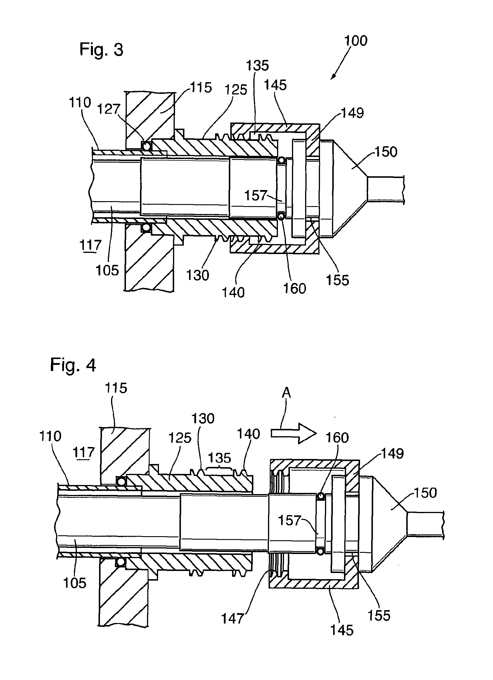
[0044]In one of its aspects, the present invention relates to a radiation source assembly comprising: an elongate radiation source; an elongate radiation transparent protective sleeve for receiving the elongate radiation source; a sleeve bolt element configured to secure the protective sleeve to a fluid treatment housing; a lamp plug element configured to: (i) be reversibly engageable with respect to the elongate radiation source, and (ii) supply electrical power to the elongate radiation source; and a first seal element configured to be moveable between a first position in which the first seal provides a substantially fluid tight seal between the sleeve bolt element and the lamp plug element and a second position in which the sleeve bolt element and the lamp plug element are unsealed upon non-rotational retraction of the lamp plug element in a direction substantially parallel to a longitudinal axis of the elongate radiation source.

[0045]In another of its aspects, the present invent...


PUM

PropertyMeasurementUnit
radiation transparentaaaaaaaaaa
electricalaaaaaaaaaa
electrical poweraaaaaaaaaa

Abstract

There is disclosed a coupling for a radiation source assembly that comprises an elongate radiation source and an elongate radiation transparent protective sleeve for receiving the elongate radiation source. The coupling disengages in two stages when it is desired to remove the elongate radiation source for servicing (or any other purpose). The coupling is disengaged from a first position in which a seal is made between the sleeve bolt element and the lamp plug element. When this action takes place, the lamp plug element is still secure with respect to the sleeve bolt element but since there is no seal between the two, any fluid which has flooded the elongate radiation source (e.g., due to breakage or other damage to the protective sleeve) will emerge from the coupling warning the operator not to fully disengage the lamp plug element from the sleeve bolt element. If no such fluid is seen by operator, the operator may continue to disengage the lamp plug element from the sleeve bolt element to withdraw the elongate radiation source from the elongate radiation transparent protective sleeve.

Description

CROSS-REFERENCE TO RELATED APPLICATION[0001]The present application claims the benefit under 35 U.S.C. §119(e) of provisional patent application Ser. No. 61 / 995,466, filed Apr. 11, 2014, the contents of which are hereby incorporated by reference.BACKGROUND OF THE INVENTION[0002]Field of the Invention[0003]In one of its aspects, the present invention relates to a radiation source assembly. In another of its aspects, the present invention relates to a radiation source module comprising a plurality of radiation source assemblies. Other aspects of the invention will become apparent to those of skill in the art upon reviewing the present specification.[0004]Description of the Prior Art[0005]Fluid treatment systems are known generally in the art.[0006]For example, U.S. Pat. Nos. 4,482,809, 4,872,980 and 5,006,244 [all in the name of Maarschalkerweerd and hereinafter referred to as the Maarschalkerweerd Patents] all describe gravity fed fluid treatment systems which employ ultraviolet (UV)...

Claims


Application Information

Patent Timeline
Patent Type & Authority Applications(United States)
IPC IPC(8): C02F1/32H01J5/60H01J61/36
CPCC02F1/325C02F2201/3227H01J5/60H01J61/36A61L2/08H01J61/02
Inventor PENHALE, DOUGLAS
Owner TROJAN TECH
Why Eureka
Try Eureka