
Fastening system allowing component removal after fastener system failure

a fastening system and component technology, applied in the direction of threaded fasteners, load-modified fasteners, screws, etc., can solve the problems of high failure rate of the fastening system, no longer secure the box cover, and many deliberately damaged boxes/cover units installed, etc., to achieve easy and inexpensive replacement, easy and inexpensive entry, and easy and cheap

Inactive Publication Date: 2017-01-26
CHANNELL COMML CORP
View PDF0 Cites 2 Cited by
  • Summary
  • Abstract
  • Description
  • Claims
  • Application Information

AI Technical Summary

Benefits of technology

The present invention is a fastening system for underground or buried vaults, pits, chambers, or boxes that solves the problems of previous fastening systems. It is easy and inexpensive to enter the chamber of the box without damaging the lid. The fastening system uses a nut and bolt arrangement that reduces the chance of failure, and when failure occurs, the failure mode is changed so that the vault can still be entered without damage to the cover or the box, and the failed component can be easily and cheaply replaced. The system has two types of nut retention designs: a fixed nut attachment to the box and a floating nut design that compensates for misalignment. The nut is made of a composite material, such as glass-filled nylon, which exhibits good strength but allows the nut threads to shear prior to other modes of failure. By controlling the length of thread engagement and the hole diameter relative to the bolt diameter, the fastener is able to meet torque requirements and still allow the nut threads to fail first. Appropriate lead chamfers are required to prevent fracture of the nuts. Overall, this fastening system addresses the challenges of previous systems and provides a reliable and affordable solution for securely closing underground vaults, pits, chambers, or boxes.

Problems solved by technology

This fastening system is highly prone to failure and a great many of the installed box / cover units are deliberately damaged to regain entry into the box chamber and access internal infrastructure such as copper or fiber-optic enclosures.
The damage is typically, but not limited to, breaking the corners of the cover where the bolts which are typically positioned onto opposing corners attach the cover to the box.
This of course means that the cover is no longer secured to the box and the cover is significantly weakened to the point that it would not likely pass load requirements regulated for that installation proximity to the vehicular loading.
As the cover is no longer secured by the bolts, which typically include tamper-resistant features such as “Penta” head designs which require specialized tools for access not commonly available, the utility vault is subject to vandalism, theft or unwanted damage due to the fact that ready access to the infrastructure which was intended to be protected by such security features is readily available.
Failure of the fastening systems typically occurs by two mechanisms wherein either the bolt and nut becomes seized together and the bolt cannot be turned for removal, or the bolt and nut become seized and the nut breaks free of its retainer and spins with the bolt as it is turned.
In some systems there is an additional failure mode where the bolt threads are stripped and the bolt cannot be removed.
All of these situations prevent removal of the cover and lead technicians to break the cover to gain access.
Further exacerbation of this problem is the recent development and deployment of advanced composite materials, used to manufacture the covers, which cannot be broken at the corners as older materials could and require extreme measures to re-enter the box if the retaining systems fail.
However, while galling can be an issue, a much larger problem is thread contamination with particulates especially sand, soil, cement and granules of polymer concrete.
Thus, most of the failures are due to contamination of the threads and the current solutions do not address this problem.

Method used


Image

  • Fastening system allowing component removal after fastener system failure
  • Fastening system allowing component removal after fastener system failure
  • Fastening system allowing component removal after fastener system failure

Examples


Embodiment Construction

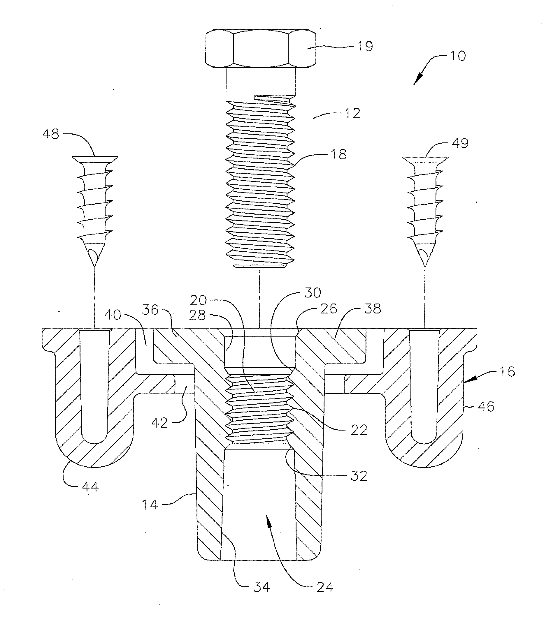
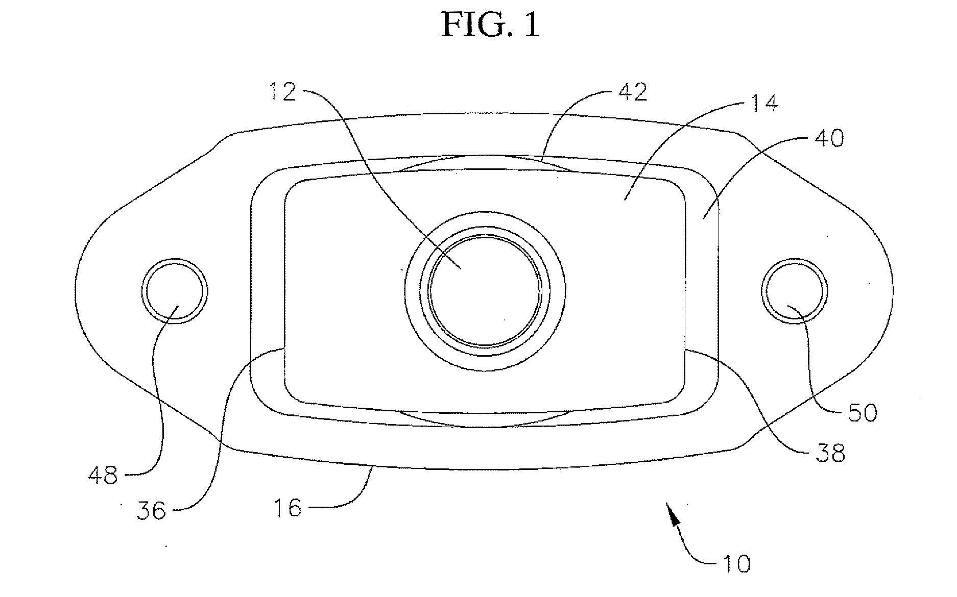
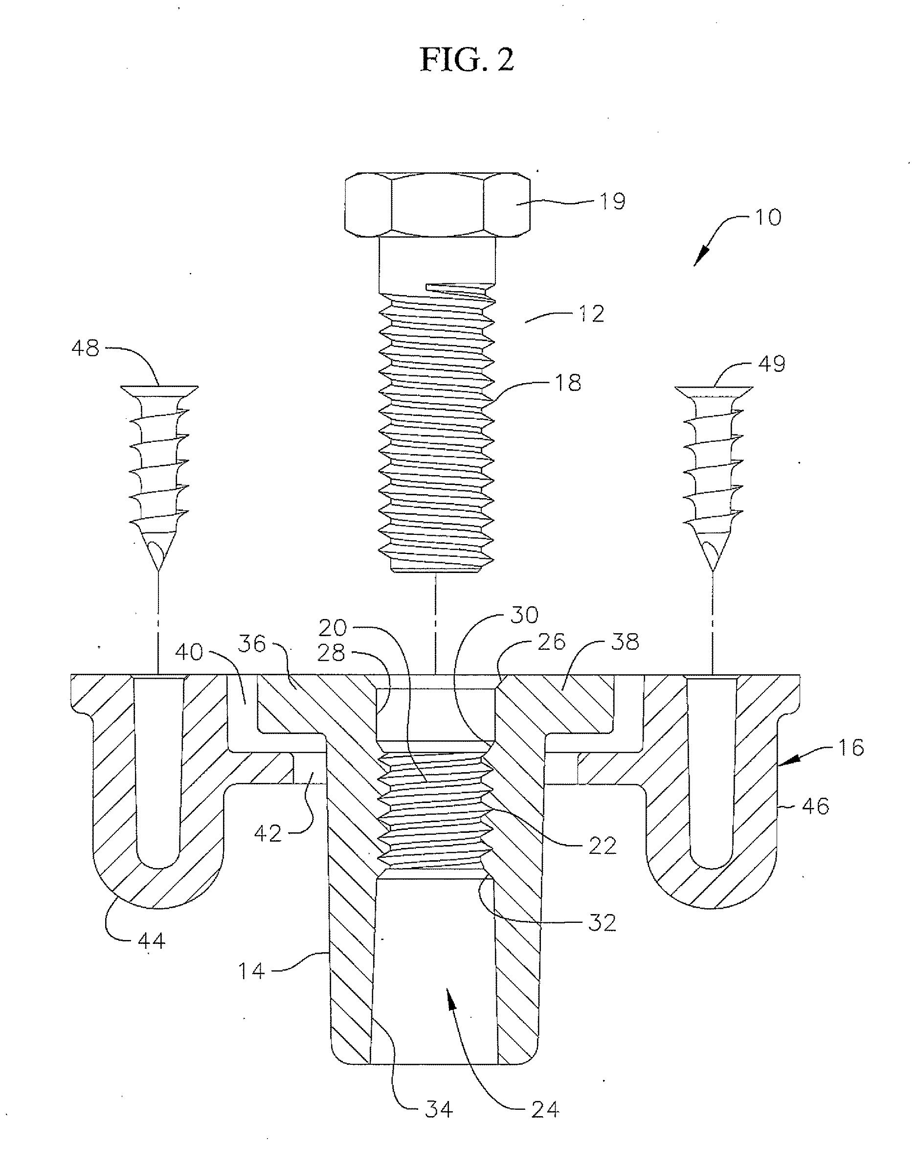
[0017]Referring to FIGS. 1 and 2 the fastening system 10 of the present invention is illustrated. The fastening system comprises a bolt 12, a nut 14 and a nut retainer 16. The fastening system 10 is utilized to attach a lid or cover to an underground or grade-level vault, pit, chamber or box which will be discussed in more detail subsequently herein. Bolt 12 is typically a lag bolt having course threads 18 for engagement with complimentary threads 20 on the nut 14 positioned in a thread engagement section 22 of a hole 24 extending through the nut. The bolt 12 includes a head 19 which can be a traditional head design or can include tamper-resistant features such as, for example, a Penta head design which requires specialized tools to manipulate. Threads 20 on the nut are of complimentary size to threads 18 on the bolt. Hole 24 extending through the nut includes a bolt lead-in chamfer 26 extending to a bolt alignment section 28 which extends to a thread lead-in chamfer 30 positioned b...


PUM


Abstract

A fastening system for attaching a cover to an underground vault having a bolt with course threads and a composite fiber reinforced polymer nut having a threaded portion extending through the nut which will fail in sheer before the nut and bolt seize. The fastening system can also include a nut retainer sized to allow the nut to float within the retainer.

Description

CROSS-REFERENCE TO RELATED APPLICATIONS[0001]This application claims the benefit of and priority to U.S. Provisional Patent Application Ser. No. 62 / 194,716 filed Jul. 20, 2015 the contents of which are incorporated herein by reference.FIELD OF THE INVENTION[0002]The Invention relates to a fastener system for a lid or cover used on an underground or grade-level vault used in various underground industries.BACKGROUND[0003]Underground or buried vaults, pits chambers or boxes used in the utilities, security, and rail line sectors or other industries can contain co-axial or optical fiber, copper cable as well as gas and power lines and other conduits, industrial valves. WI-FI antennas, etc. Vaults and pits for underground utilities often need to be opened for making repairs or for enhancing services. Typically, utility vaults and pits include a concrete, polymer concrete, or plastic lid which is opened by a tool or pick with a hook at one end. The hook is inserted through a hole in the l...

Claims


Application Information

Patent Timeline
Patent Type & Authority Applications(United States)
IPC IPC(8): F16B31/00F16B35/00E02D29/14F16B37/00
CPCF16B31/00F16B37/00E02D2600/20E02D29/14F16B35/00F16B39/02F16B31/021F16B37/042F16B5/0225F16B37/005F16B37/044F16B33/006
Inventor LEMACKS, MICHAEL A.
Owner CHANNELL COMML CORP
Learn More