Vibration damping device

a damping device and vibration technology, applied in the direction of torsion springs, couplings, gearing, etc., can solve the problem of relatively complex structure of the damping device, and achieve the effect of simple, effective and economical

Active Publication Date: 2017-01-26
VALEO EMBRAYAGES SAS
View PDF42 Cites 1 Cited by
  • Summary
  • Abstract
  • Description
  • Claims
  • Application Information

AI Technical Summary

Benefits of technology

[0010]An object of the invention is in particular to provide a simple, effective, and economical solution to this problem.

Problems solved by technology

A damper of this kind has a relatively complex structure.

Method used


Image

  • Vibration damping device
  • Vibration damping device
  • Vibration damping device

Examples


Embodiment Construction

)

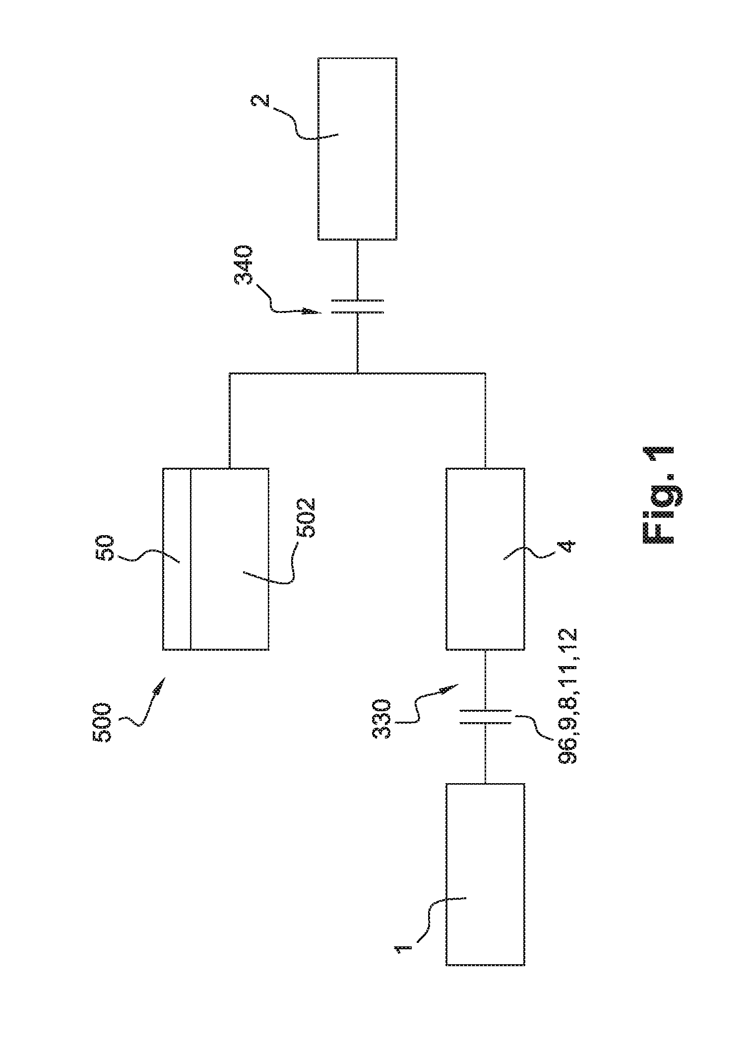
[0087]FIG. 1 illustrates a transmission assemblage disposed between a combustion engine 1 and a gearbox 2, according to an embodiment of the invention. The transmission assemblage has a first friction clutch 330, a torsional damping device 4, an electric machine 500 comprising a stator 501 and a rotor 502, and a second friction clutch 340.

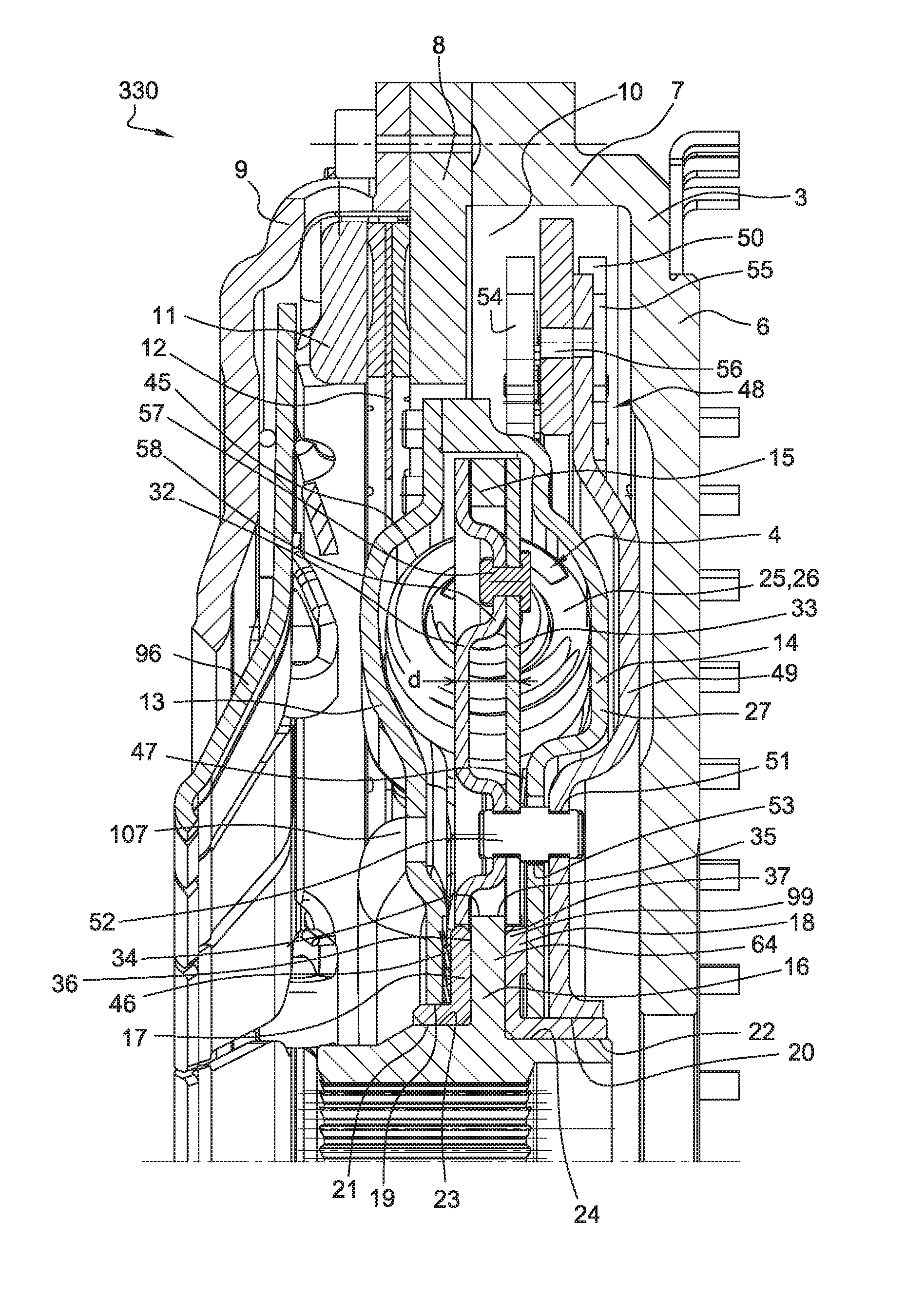
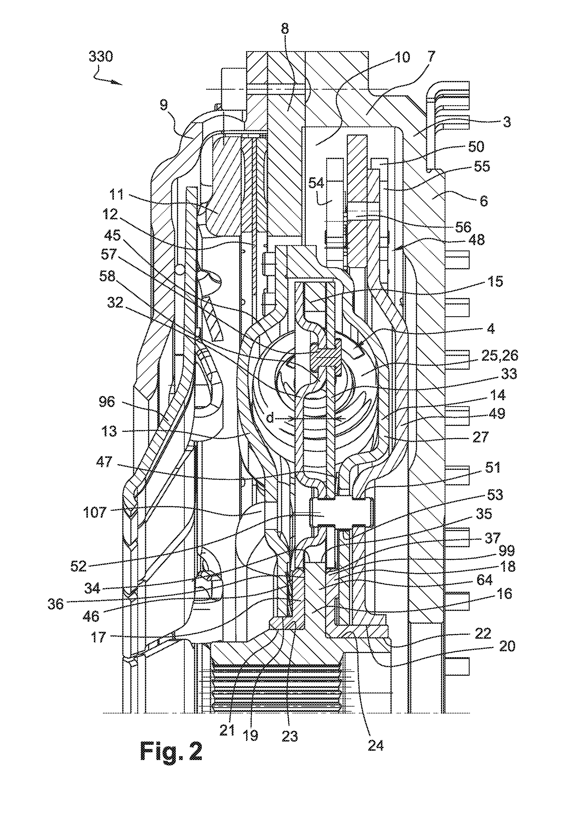
[0088]FIG. 2 illustrates first friction clutch 330 associated with torsional damping device 4. First friction clutch 330 is connected to an inertial wheel 3. Inertial wheel 3 has a first annular region 6 extending radially, and a cylindrical region 7 extending axially toward to the rear from the outer periphery of first annular region 6. A second cylindrical region 8 and an annular cover 9 are fastened on cylindrical region 7. First annular region 6, cylindrical region 7, and second annular region 8 define an annular chamber 10.

[0089]Inertial wheel 3 also has orifices (not depicted) configured in first annular region 6. Fastening screws (not depic...


PUM


Abstract

A vibration damping device (330) for a motor vehicle, having:
    • a first element (13, 14) and a second element (15, 16) that are rotationally movable around an axis X and capable of transmitting a torque;
    • at least one group of elastic members (25, 26) mounted between the first element and the second element and acting against rotation of the first element and second element with respect to one another;
    • a phasing member (32, 33), rotationally movable around the axis X and constituted by a first portion (32) and a second portion (33), for arranging the elastic members of that group in series so that the elastic members of each group deform in phase with one another.

Description

CROSS-REFERENCE TO RELATED APPLICATIONS AND CLAIM TO PRIORITY[0001]This application is related to Patent Application No. 1557106 filed Jul. 24, 2015 in France, the disclosure of which is incorporated herein by reference and to which priority is claimed.FIELD OF THE INVENTION[0002]The present invention relates to a torsional damping device, in particular for a motor vehicle transmission system.BACKGROUND OF THE INVENTION[0003]In such an application the torsional damping device can be integrated into a transmission assemblage comprising a friction clutch capable of selectively connecting the combustion engine to the gearbox, in order to filter vibrations due to irregularities of the engine.[0004]As a variant, in such an application the torsional damping device can be integrated into a dual mass flywheel, into a friction disk of the clutch, or into a hydrodynamic torque converter.[0005]The invention also relates to a transmission assemblage for a motor vehicle of the hybrid type, in wh...

Claims


Application Information

Patent Timeline
Patent Type & Authority Applications(United States)
IPC IPC(8): F16D13/58B60K6/387F16D13/38F16D3/12F16F15/14
CPCF16D13/58F16D3/12F16F15/145F16D13/38Y10S903/902F16H2045/0226F16H2045/0263F16H45/02B60K6/387F16F15/30F16F15/315F16F2222/08F16F15/13492F16F15/12366F16F15/1337F16F2238/024F16F2236/08F16F15/12353F16F15/13469
Inventor LEBAS, GILLESCOMMEINE, EMMANUELVERHOOG, ROELDUTIER, IVANLAFORGE, THIBAULTHENNEBELLE, MICHAEL
Owner VALEO EMBRAYAGES SAS
Why Eureka
Try Eureka