
Arc management with voltage reversal and improved recovery

a technology of arc management and voltage reversal, applied in the field of power supplies, can solve the problems of increasing system costs, inability to provide expedient arc mitigation, and affecting the quality of processed films, so as to reduce the current level

Active Publication Date: 2017-01-26
AES GLOBAL HLDG PTE LTD
View PDF0 Cites 1 Cited by
  • Summary
  • Abstract
  • Description
  • Claims
  • Application Information

AI Technical Summary

Benefits of technology

The patent describes a method for managing arcs in a plasma load. The method involves using a power supply to provide current to the plasma load at a first voltage polarity. An energy storage device is then energized to create a reverse polarity voltage that is at least as great as the first voltage polarity. When an arc is detected, power is applied from the energy storage device to the plasma load with the reverse polarity voltage to decrease the level of current provided to the plasma load. To prevent damage, the reverse polarity voltage is not applied if the current decreases to zero. After the arc is extinguished, power is reapplied to the plasma load at the first voltage polarity to resume processing. The technical effect of this method is to reduce the risk of damage to the plasma load during an arc event and to improve the manufacturing process' efficiency and reliability.

Problems solved by technology

If not extinguished quickly, arcs can be very detrimental to the process and the quality of the processed film.
These types of systems are effective to some extent, but are unable to provide the expedient arc mitigation often necessary in present processing environments.
Although, these systems enable arcs to be extinguished relatively quickly, the second-power supply adds substantial cost to the system and substantially increases a risk of failure.
Tapped inductors that can handle higher currents and provide the desired low-leakage inductance, however, are relatively expensive.
And implementing cable with a sufficiently low inductance is also costly—especially at higher currents.
Although present devices are functional for many applications, they are not sufficient for many implementations or are otherwise unsatisfactory.

Method used


Image

  • Arc management with voltage reversal and improved recovery
  • Arc management with voltage reversal and improved recovery
  • Arc management with voltage reversal and improved recovery

Examples


Embodiment Construction

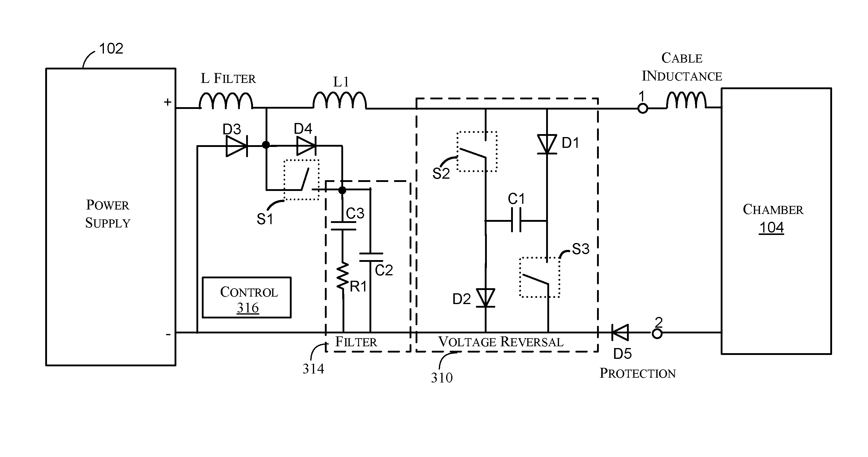
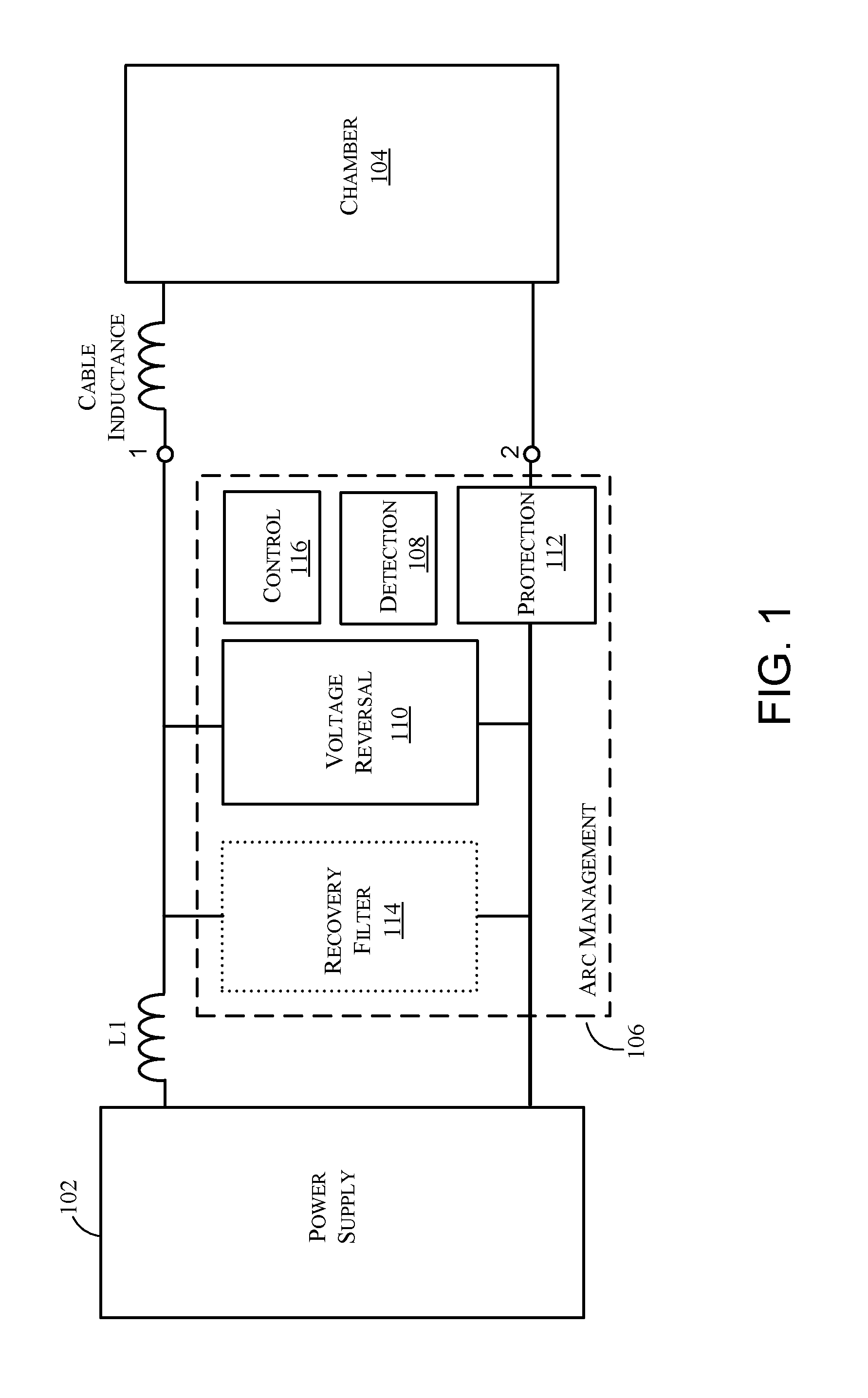
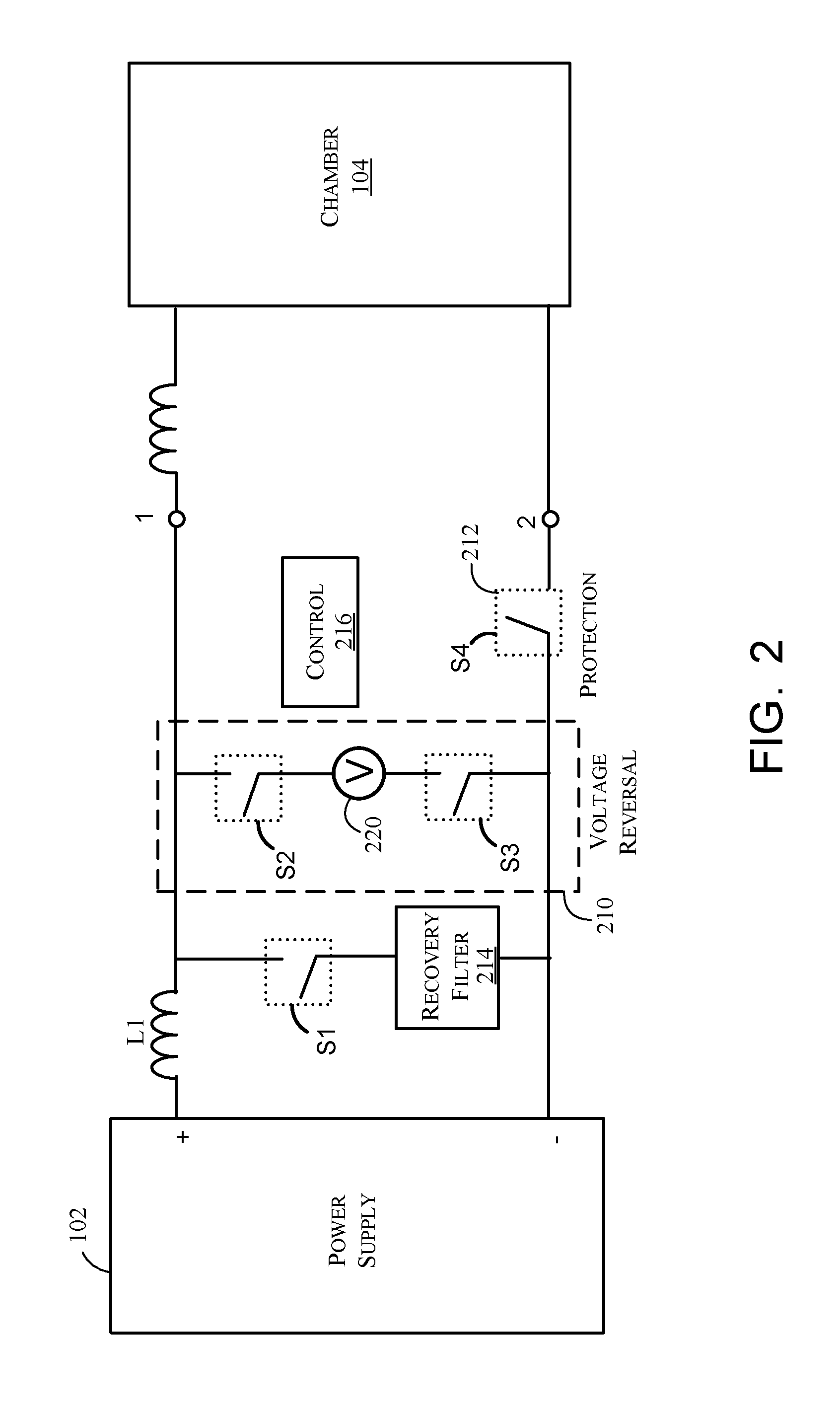
[0017]Referring now to the drawings, where like or similar elements are designated with identical reference numerals throughout the several views, and referring in particular to FIG. 1, it illustrates a block diagram depicting an exemplary embodiment of the invention. Shown is a power supply 102 (e.g., a DC, pulse-width modulated voltage source) that is disposed to apply pulsed DC power to a plasma chamber 104 with a supply cable to facilitate any of a variety of plasma processing applications known to those of skill in the art. As depicted, the power supply 102 is also connected to arc management components 106, which may be implemented as part of an integrated unit (e.g., within the same housing) with the power supply 102.

[0018]As shown, the arc management components 106 include a detection component 108, a voltage reversal component 110, a protection component 112, an optional recovery filter 114, and a control portion 116. In general, the arc management components 106 function t...


PUM


Abstract

Systems and methods for arc handling in plasma processing operations are disclosed. The method includes providing current with a power supply to a plasma load at a first voltage polarity and energizing an energy storage device so when it is energized, the energy storage device applies a reverse polarity voltage that has a magnitude that is as least as great as the first voltage polarity. When an arc is detected, power is applied from the energy storage device to the plasma load with a reverse polarity voltage that has a polarity that is opposite of the first voltage polarity, the application of the reverse polarity voltage to the plasma load decreases a level of the current that is provided to the plasma load.

Description

PRIORITY[0001]The present application for patent is a Continuation of patent application Ser. No. 14 / 012,847 entitled “ARC MANAGEMENT WITH VOLTAGE REVERSAL AND IMPROVED RECOVERY” filed Aug. 28, 2013, pending, which claims priority to Provisional Application No. 61 / 695,914 entitled “ARC MANAGEMENT WITH VOLTAGE REVERSAL AND IMPROVED RECOVERY” filed Aug. 31, 2012, and assigned to the assignee hereof and hereby expressly incorporated by reference herein.FIELD OF THE INVENTION[0002]This invention relates generally to power supplies for plasma processing applications, and more particularly to systems and methods to limit arcing therein.BACKGROUND OF THE INVENTION[0003]In plasma processing applications arcs are known to develop when a discharge occurs between a point on a cathode where charge has accumulated and a point on the anode. If not extinguished quickly, arcs can be very detrimental to the process and the quality of the processed film.[0004]Past approaches to arc control in plasma ...

Claims


Application Information

Patent Timeline
Patent Type & Authority Applications(United States)
IPC IPC(8): H01J37/32H01J37/24H01J37/244
CPCH01J37/32944H01J2237/244H01J37/24H01J37/244H05H1/36H05H1/48H01J2237/0206H05H1/3494
Inventor WALDE, HENDRIKPANKRATZ, JOSHUA BRIANCHRISTIE, DAVIDKOWAL, BRIAN D.
Owner AES GLOBAL HLDG PTE LTD
Learn More