Antenna device and coil component used therein

a technology of coil components and antennas, applied in the field of antenna devices, can solve the problems of difficult to increase aperture sizes, and difficult to dispose of antennas, and achieve the effects of easy design and implementation of coil components, large apertures, and enhanced coil components

Active Publication Date: 2017-01-26
TDK CORPARATION
View PDF3 Cites 2 Cited by
  • Summary
  • Abstract
  • Description
  • Claims
  • Application Information

AI Technical Summary

Benefits of technology

[0020]According to the present invention, a coil element having as large an aperture as possible within a limited space like, e.g., an inside of a housing of a mobile wireless device can be easily formed. Thus, the inductance of the coil component can be enhanced. Further, according to the present invention, the design of the antenna component is an expansion of design of the circuit on the first substrate, so that it is possible to easily design and implement the coil component without the need of preparing discrete coil components.
[0021]Further, a mobile wireless device according to the present invention includes an antenna device having the above-described features, wherein the first substrate is a main circuit board of the mobile wireless device. According to the present invention, the design of the antenna device is an expansion of design of the circuit on the first substrate, so that it is possible to easily design and implement the antenna device without the need of preparing discrete coil components.
[0022]According to the present invention, there can be provided an antenna device suitable for near field communication in which a solenoid antenna coil having as large an aperture as possible can be installed within a limited space like an inside of a housing of the mobile wireless device and a coil component suitable for constituting such an antenna device.

Problems solved by technology

However, the metal shield blocks radio waves in general, so that when an antenna needs to be provided, it needs to be disposed at a position not covered with the metal shield.
Thus, when the metal shield covers a wide range, it is difficult to dispose the antenna.
In a case where the housing itself of the mobile wireless device serves also as the metal shield as described above, a consideration needs to be made to prevent an antenna from being affected by the metal shield even if the antenna is a solenoid antenna, and when the metal shield covers a wide range, it is difficult to dispose the antenna.
Further, an aperture size of a known solenoid antenna wound around an outer peripheral surface of a winding core of a magnetic core or the like is restricted by a cross-sectional size of the magnetic core, making it difficult to increase the aperture size.
Further, the solenoid antenna has too much directivity and, in addition, when a size of the antenna is reduced, it cannot generate a large magnetic flux loop that can cross a counterpart antenna, resulting in a short communication distance, which poses a practical problem for the solenoid antenna as a near field communication antenna.
For example, when the entire back surface of the housing of the mobile wireless device is covered with the metal cover layer, durability and designability of the mobile wireless device can be further improved; in this case, however, it is impossible to provide the antenna coil at a position not covered with the metal cover layer.

Method used


Image

  • Antenna device and coil component used therein
  • Antenna device and coil component used therein
  • Antenna device and coil component used therein

Examples


Embodiment Construction

[0030]Preferred embodiments of the present invention will be explained below in detail with reference to the accompanying drawings.

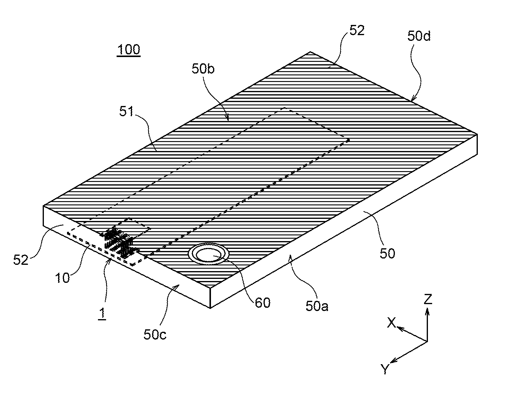
[0031]FIG. 1 is a perspective view schematically illustrating a configuration of a mobile wireless device including an antenna device according to an embodiment of the present invention.

[0032]As illustrated in FIG. 1, a mobile wireless device 100 according to the present embodiment is, e.g., a smartphone and has a very thin housing 50. In FIG. 1, a back surface 50b of the housing 50 faces upward, and a front surface 50a of the housing 50 on which a display is mainly provided faces downward. The housing 50 is made of a combination of a resin and a metal, and substantially the entire surface of the back surface 50b of the housing 50 is formed as a metal cover layer 51. One end surface (upper end surface 50c) and the other end surface (lower end surface 50d) in a longitudinal direction (Y-direction), which are perpendicular to the back surface 50b of the ho...


PUM


Abstract

An antenna device is provided with first and second substrates opposed to each other, one or more first wiring patterns provided on the first substrate, one or more second wiring patterns provided on the second substrate, and a plurality of connection conductors each connecting an end portion of its corresponding first wiring pattern and an end portion of its corresponding second wiring pattern. The first wiring patterns, second wiring patterns and the plurality of connection conductors constitute an antenna coil.

Description

BACKGROUND OF THE INVENTION[0001]Field of the Invention[0002]The present invention relates to an antenna device and, more particularly, to an antenna device suitable for NFC (Near Field Communication). The present invention further relates to a coil component used in such an antenna device.[0003]Description of Related Art[0004]In recent years, a mobile wireless device such as a smartphone is equipped with an RFID (Radio Frequency Identification: individual identification by radio waves) system, and further equipped with, as a communication means of the RFID, an antenna for performing the near field communication with a reader / writer and the like.[0005]Further, such a mobile wireless device is provided with a metal shield in order to protect a built-in circuit from external noise and prevent unnecessary radiation of noise generated inside the device. In particular, recently, in view of thinning, light-weighting, durability against impacts such as drops, designability, and the like, a...

Claims


Application Information

Patent Timeline
Patent Type & Authority Applications(United States)
IPC IPC(8): H01Q7/06H04B5/00H01Q1/24
CPCH01Q7/06H04B5/0062H04B5/0081H01Q1/243H01Q1/38H01Q7/00
Inventor TOMONARI, TOSHIOKOMACHI, TOSHIFUMIASOU, HIROHUMI
Owner TDK CORPARATION
Why Eureka
Try Eureka