Translucent cannula with self contained cooling function and enhanced visibilty for ablation catheter

a cannula and transparent technology, applied in the field of medical technology, can solve the problems of high probability of re-occurrence, and achieve the effect of vastly enhancing the visibility of the cannula and improving navigation

Inactive Publication Date: 2017-02-02
1389251 ONTARIO INC
View PDF4 Cites 5 Cited by
  • Summary
  • Abstract
  • Description
  • Claims
  • Application Information

AI Technical Summary

Benefits of technology

[0014]The fluid conducting channels have fluid-carrying dimensions sufficient to transport sufficient liquid at 15° C. through the channels to cool both tissue adjacent the channels and the tip during emission from a tissue ablating laser within the thermal energy emitting tip. The composition of the one-piece cannula is at least translucent / transparent to at least 50% of infrared radiation between 900-1200 nm emitted from within the cannula at the thermal energy-emitting tip. The composition of the one-piece cannula should have a melting temperature of at least 150° C. The same fluid channels can be used to improve navigation when using MRI guided interstitial placement of cannula by pumping paramagnetic agents such as dilute gadolinium to vastly enhance the visibility of the cannula, speed placement of the thermal generating tip to the optimal site.

Problems solved by technology

In many cases, to prevent or reduce the risk of thermally injuring the vital organs or tissue, the physician will opt to discontinue the procedure, or prematurely stop the procedure, resulting in a high likelihood of re-occurrence.

Method used


Image

  • Translucent cannula with self contained cooling function and enhanced visibilty for ablation catheter
  • Translucent cannula with self contained cooling function and enhanced visibilty for ablation catheter
  • Translucent cannula with self contained cooling function and enhanced visibilty for ablation catheter

Examples


Embodiment Construction

[0025]In this enabling disclosure, specific dimensions, values and numbers may be used to assure compliance with all degrees of legal and technical requirements. Thee specifics should not be considered as limiting the generic disclosure of technology and the invention provided herein.

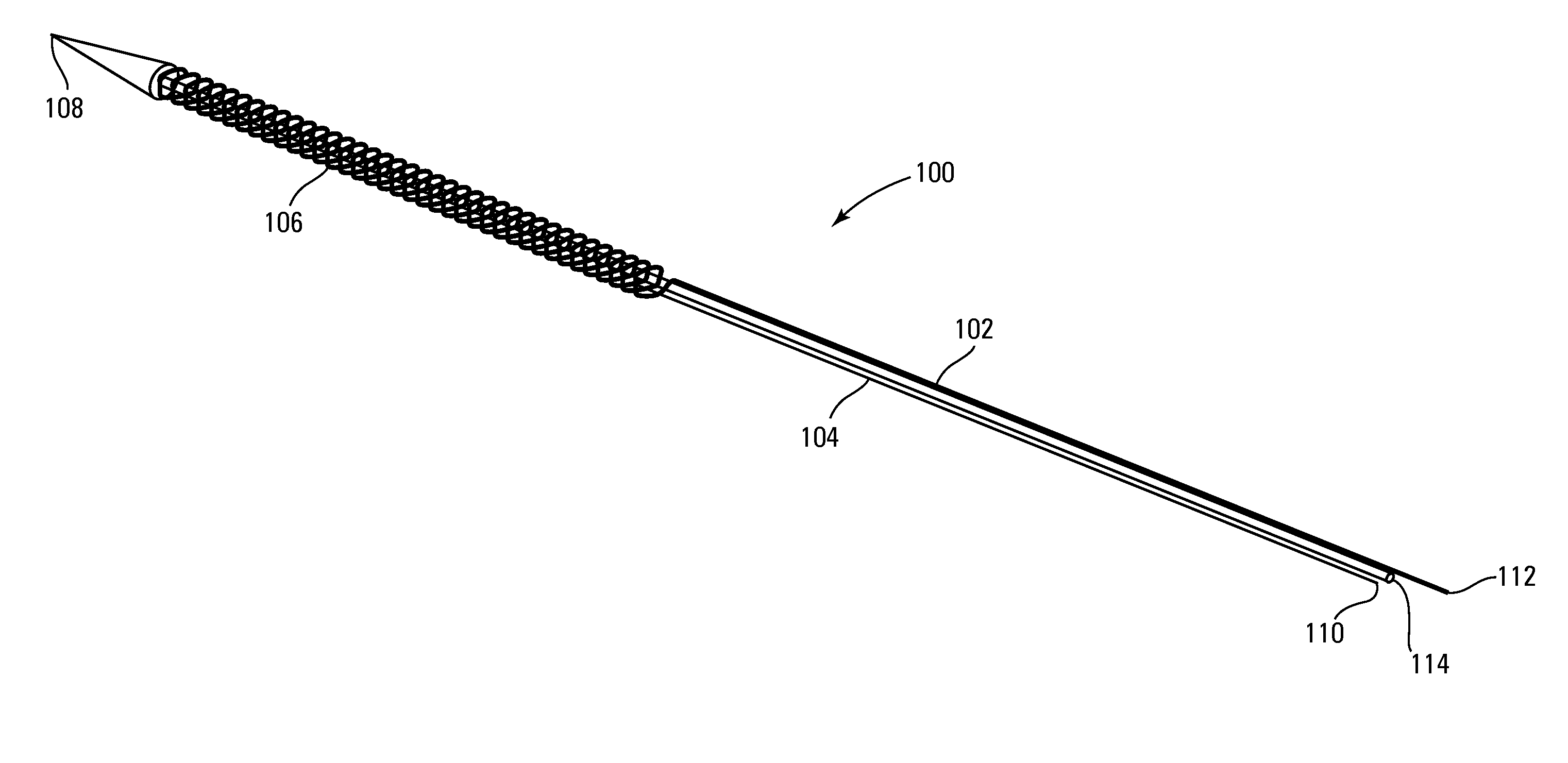
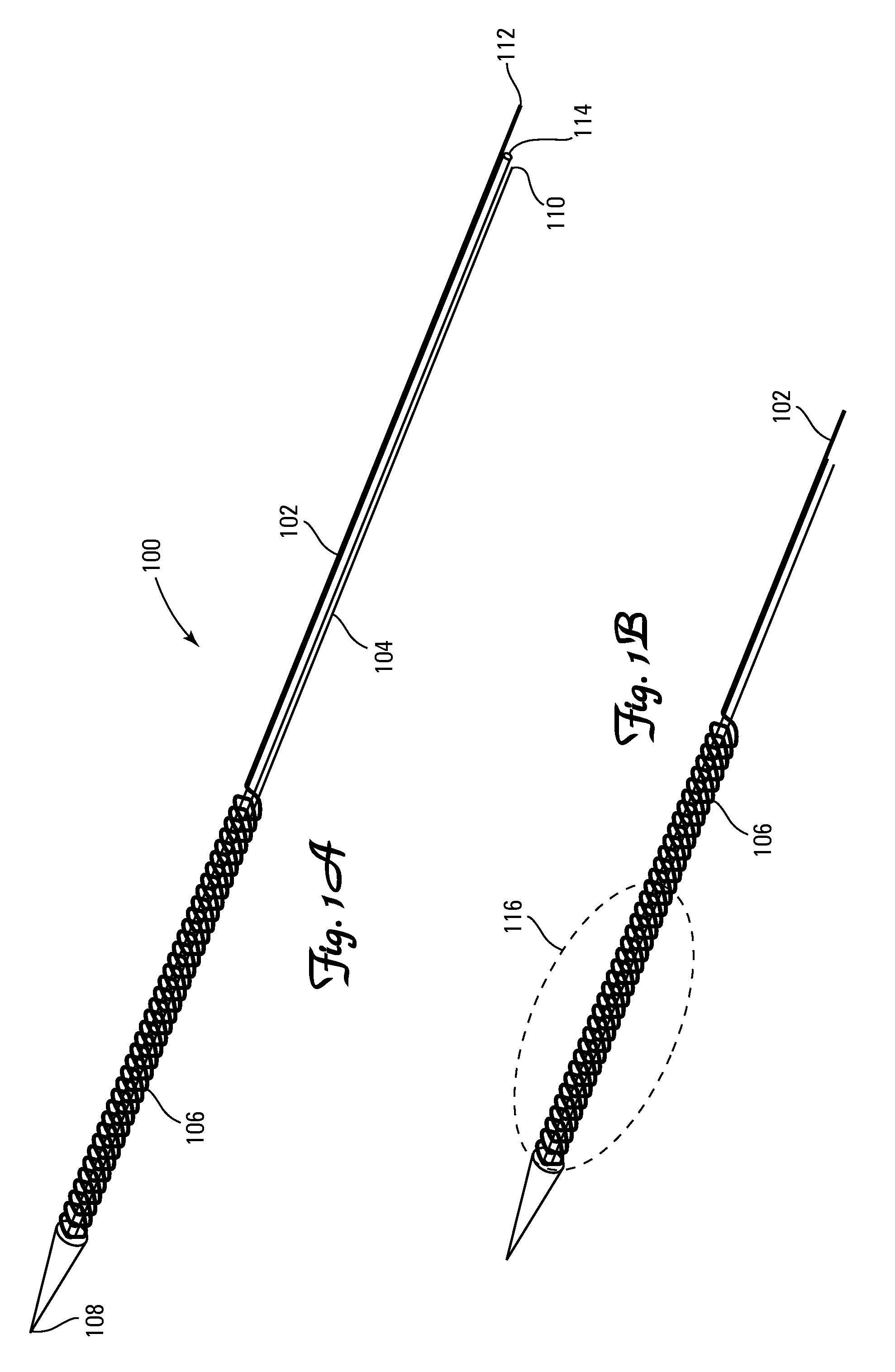
[0026]A component is enabled herein for a thermal tool, or tissue ablation or cauterizing components for use in magnetic resonance image-guided laser ablation / cauterization / devascularisation. The component may include. By way of non-limiting examples:

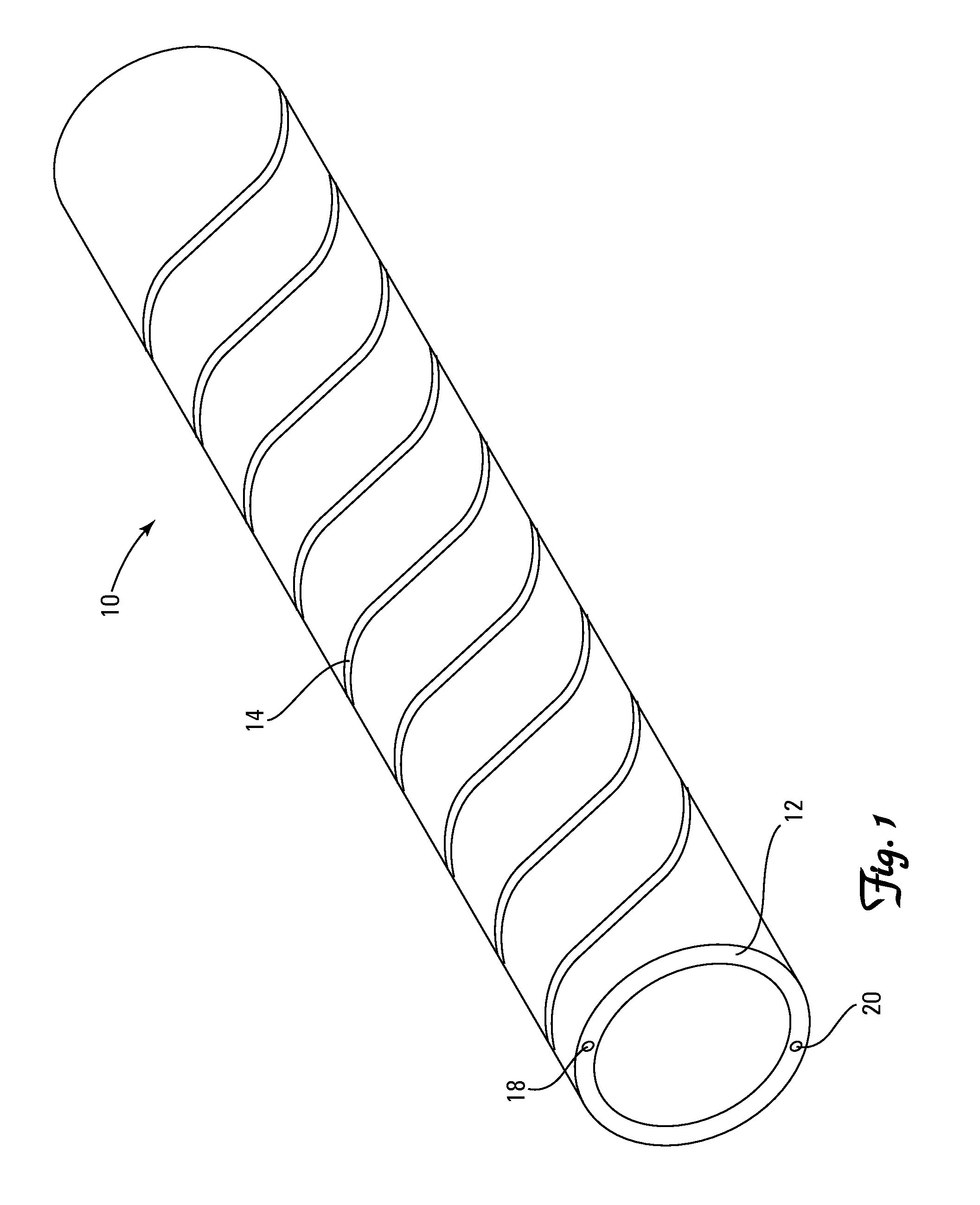
[0027]a) a one-piece cannula having at least one laser-transmitting fiber fixed thereto;

[0028]b) the one-piece cannula comprising a composition having a proximal insertion end and a thermal energy-emitting tip; and

[0029]c) fluid conducting channels fixed to the energy-emitting tip;

[0030]d) a one piece cannula with a distal quick connect locking mechanism to lock the cannula securely in place to the distal mechanized insertion plate plus at least two stabili...


PUM


Abstract

A component for use in magnetic resonance image-guided laser ablation has:
    • d) a one-piece cannula having at least one laser-transmitting fiber fixed thereto;
    • e) the one-piece cannula comprising a composition having a proximal insertion end and a thermal energy-emitting tip; and
    • f) fluid conducting channels fixed to the energy-emitting tip.
The fluid conducting channels have fluid-carrying dimensions sufficient to transport sufficient liquid at 15° C. through the channels to cool both tissue adjacent the channels and the tip during emission from a tissue ablating laser within the thermal energy emitting tip. The composition of the one-piece cannula is at least translucent/transparent to at least 50% of infrared radiation between 900-1200 nm emitted from within the cannula at the thermal energy-emitting tip. The composition of the one-piece cannula should have a melting temperature of at least 150° C.

Description

BACKGROUND OF THE INVENTION[0001]1. Field of the Invention[0002]The present invention relates to the field of medical technology, and especially laser ablation technology, including both instrumentality and methods.[0003]2. Background of the Art[0004]The delivery of radio frequency (RF) energy to target regions within tissue is known for a variety of purposes of particular interest to the present inventions. In one particular application, RF energy may be delivered to diseased regions (e.g., tumors) in tissue for the purpose of tissue necrosis. RF ablation of tumors is currently performed within one of two core technologies.[0005]The first technology uses a single needle electrode, which when attached to a RF generator, emits RF energy from the exposed, uninsulated portion of the electrode. This energy translates into ion agitation, which is converted into heat and induces cellular death via coagulation necrosis. The second technology utilizes multiple needle electrodes, which have ...

Claims


Application Information

Patent Timeline
Patent Type & Authority Applications(United States)
IPC IPC(8): A61B18/22A61B34/00A61B34/30A61M5/00A61B34/20
CPCA61B18/22A61B2018/00547A61B34/20A61B34/30A61B34/70A61B2018/00029A61B2018/00059A61B2034/2051A61B2034/2065A61B5/055A61B2034/301A61B2018/00642A61B2018/00577A61B2018/00595A61M5/007A61B2018/005A61B2090/306A61B2090/374A61B2090/3954A61B2018/206
Inventor TRACHTENBERG, JOHN
Owner 1389251 ONTARIO INC
Why Eureka
Try Eureka