Backlight unit and display device comprising same

Active Publication Date: 2017-02-02
KOOKMIN UNIV IND ACAD COOP FOUND
View PDF6 Cites 0 Cited by
  • Summary
  • Abstract
  • Description
  • Claims
  • Application Information

AI Technical Summary

Benefits of technology

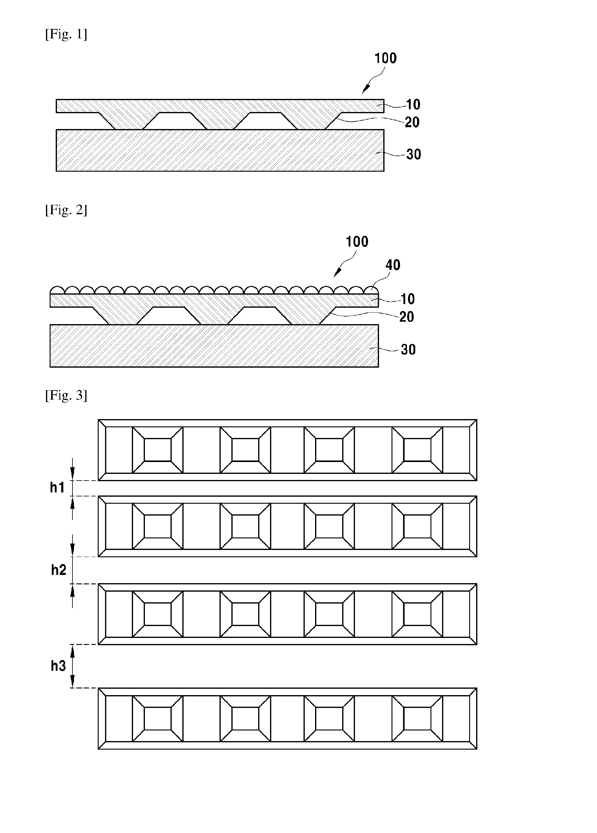
[0011]According to one embodiment of the present invention, a backlight can be fabricated without an addition of a separate prism sheet or a diffusion sheet by coupling a light guiding plate, in which a micro lenticular pattern or a micro prism pattern is formed, to one optical sheet, and therefore, there is an advantage in that a backlight having minimal parts can be produced. Particularly, in a structure of the light guiding plate according to one embodiment of the present invention, light incident on an inside of the light guiding plate corresponds to a total reflection condition on both top and bottom surfaces of the light guiding plate, and therefore there is almost no loss of light. Further, a structure of the backlight unit (BLU) may have a minimal number of light interfaces, and therefore there is an advantage in that light utilization efficiency can be maximized.
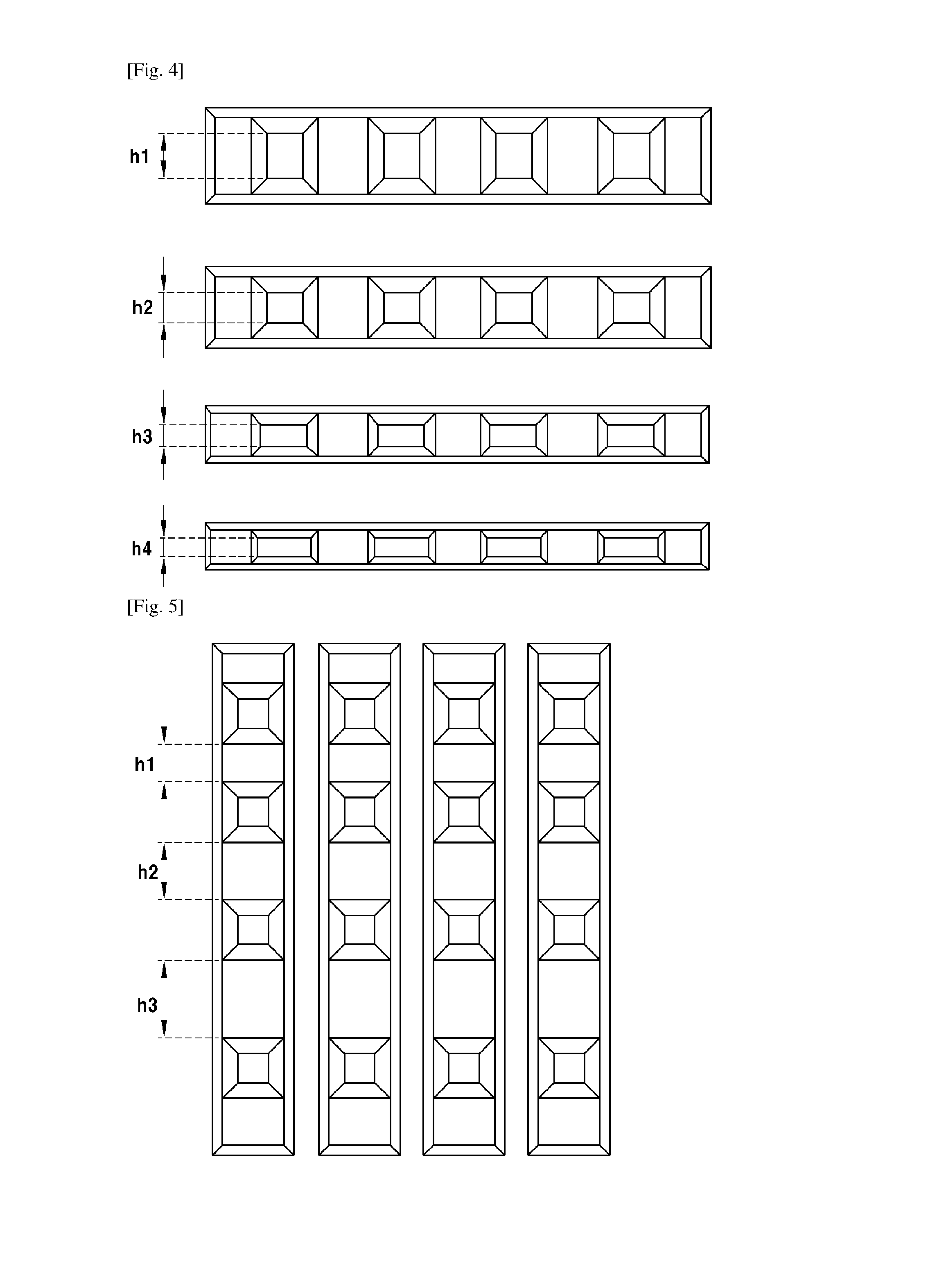
[0012]According to one embodiment of the present invention, as a size of the BLU increases and a size of the light guiding plate increases, density difference of a structure formed on the optical sheet can be generated with respect to positions between an incident portion and a terminal portion of the light source. In this case, a problem of micro pattern visibility is eliminated, and a uniform quality of a planar light source can be enhanced. Particularly, by integrally forming the optical sheet and the light guiding plate and removing a diffusion sheet and a prism sheet, miniaturization and thinness of the BLU can be realized.
[0013]According to one embodiment of the present invention, a light extraction structure with high efficiency which avoids a method of light scattering is implemented, and since the optical sheet according to the present invention is coupled to the light guiding plate, a BLU can be

Problems solved by technology

However, liquid crystals included in a display device of an LCD device do not emit light by themselves and only perform a function of simply transmitting or blocking light according to an applied electric signal.
When the diffusion sheet and the prism sheet are separately provided as thus, there may be problems in that not only fabrication of a light, thin, short, and small BLU is difficult due to an increase in the number of part

Method used


Image

  • Backlight unit and display device comprising same
  • Backlight unit and display device comprising same
  • Backlight unit and display device comprising same

Examples


Embodiment Construction

[0028]Hereinafter, embodiments of the present invention are described below in sufficient detail so that those of ordinary skill in the art can embody and practice the inventive concept. However, the present invention is not limited to the embodiments disclosed and may be implemented in various different forms. Further, in the drawings, portions irrelevant to the descriptions are omitted in order to clearly describe the present invention, and the same or corresponding elements will be given the same reference numbers throughout the specification.

[0029]Throughout the entire specification, it should be understood that when an element is referred to as being “connected” or “coupled” to another element, it can be directly connected to the another element or may be electrically coupled to the other element with intervening elements.

[0030]Throughout the entire specification, it should be understood that when a first element is referred to as being “on” a second element, the first element ...


PUM


Abstract

The described technology relates to a backlight unit and a display device comprising including the backlight unit. In one aspect, the backlight unit includes a light source and a light guiding plate configured to guide light emitted from the light source, The backlight unit also includes an optical sheet integrally formed with the light guiding plate and including a micro pattern configured to emit light reflected from the light guiding plate.

Description

TECHNICAL FIELD[0001]The present invention relates to a backlight unit and a display device comprising the backlight unit.BACKGROUND ART[0002]Recently, as various portable electronic devices, such as mobile phones, personal digital assistants (PDAs), and notebook computers, develop, need for a light, thin, short, and small flat panel display device applicable to such devices has been gradually increasing. As these flat panel display devices, liquid crystal displays (LCDs), plasma display panels (PDPs), field emission displays (FEDs), vacuum fluorescent displays (VFDs), and the like are actively being studied, and currently, among them, LCDs in particular have the spotlight because of a mass-production technology, availability of a driving unit, implementation of high definition, implementation of a large screen, and the like.[0003]An LCD device displays an image using liquid crystals interposed between two sheets of electrodes. However, liquid crystals included in a display device o...

Claims


Application Information

Patent Timeline
IPC IPC(8): F21V8/00
CPCG02B6/005G02B6/0036G02B5/02G02B5/04G02B6/0051
Inventor LEE, JAE GABSOH, HOE SUBKWON, JIN HYUK
Owner KOOKMIN UNIV IND ACAD COOP FOUND
Why Eureka
Try Eureka