Multi-Functional Structure for Thermal Management and Prevention of Failure Propagation
a multi-functional structure and thermal management technology, applied in the direction of cell components, vent arrangements, lighting and heating apparatus, etc., can solve the problems of catastrophic failure, low cycle lifetime of lithium-ion batteries made of arrays of cells, and reliability issues
- Summary
- Abstract
- Description
- Claims
- Application Information
AI Technical Summary
Benefits of technology
Problems solved by technology
Method used
Image
Examples
example 1
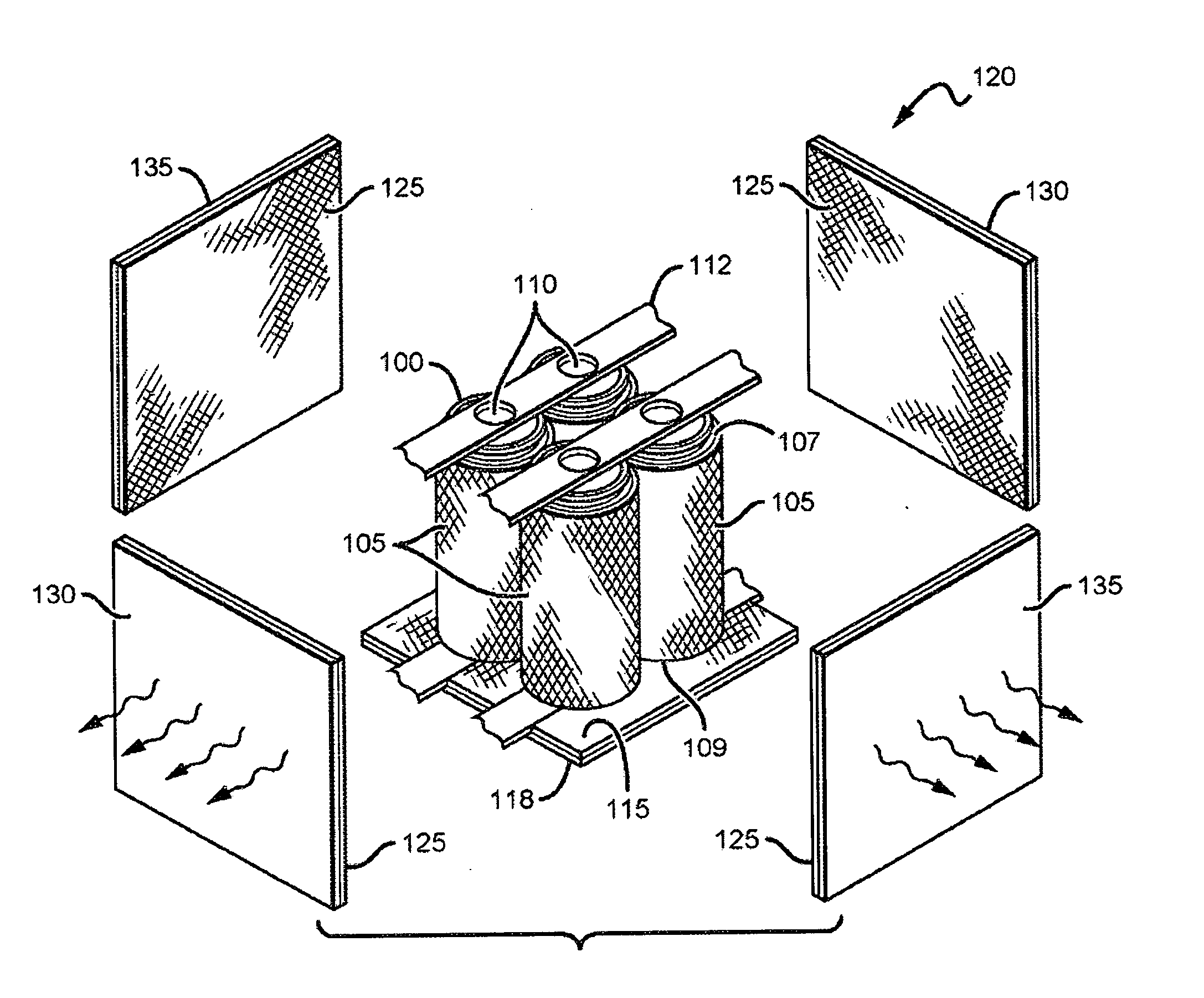
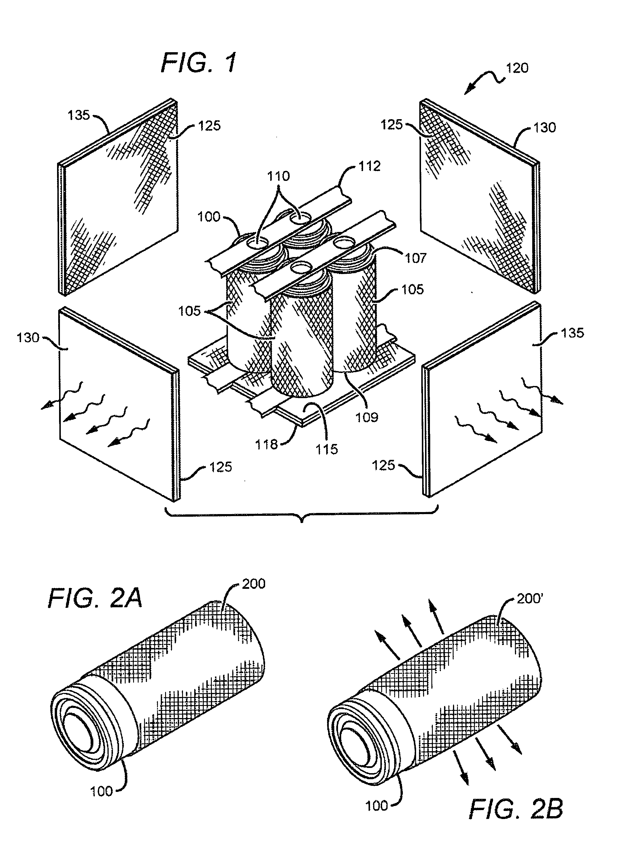
[0058]A rechargeable lithium iron phosphate (LFP) battery, cylindrical in shape with nominal dimensions 26 mm in diameter and 65 mm in height (26650 LFP) is placed inside a vapor-tight enclosure. Electrical leads are connected to the cell using feedthroughs in the cover of the enclosure. Certain amount of dielectric liquid 3M NOVEC 7200 is placed at the bottom of the enclosure. The battery is first charged at 0.5 C rate to 3.65 V and then further charged at constant voltage with the current decreasing over time down to 65 mA. The battery is then discharged fully to 0% SOC under a constant resistance load, starting with 10 Amp current. The temperature of the cell is recorded as a function of time during the discharge. The ambient temperature around the enclosure is kept at 40° C. The temperature of the cell wall is rising as shown in FIG. 10 by 23° C. at 0% SOC.
example 2
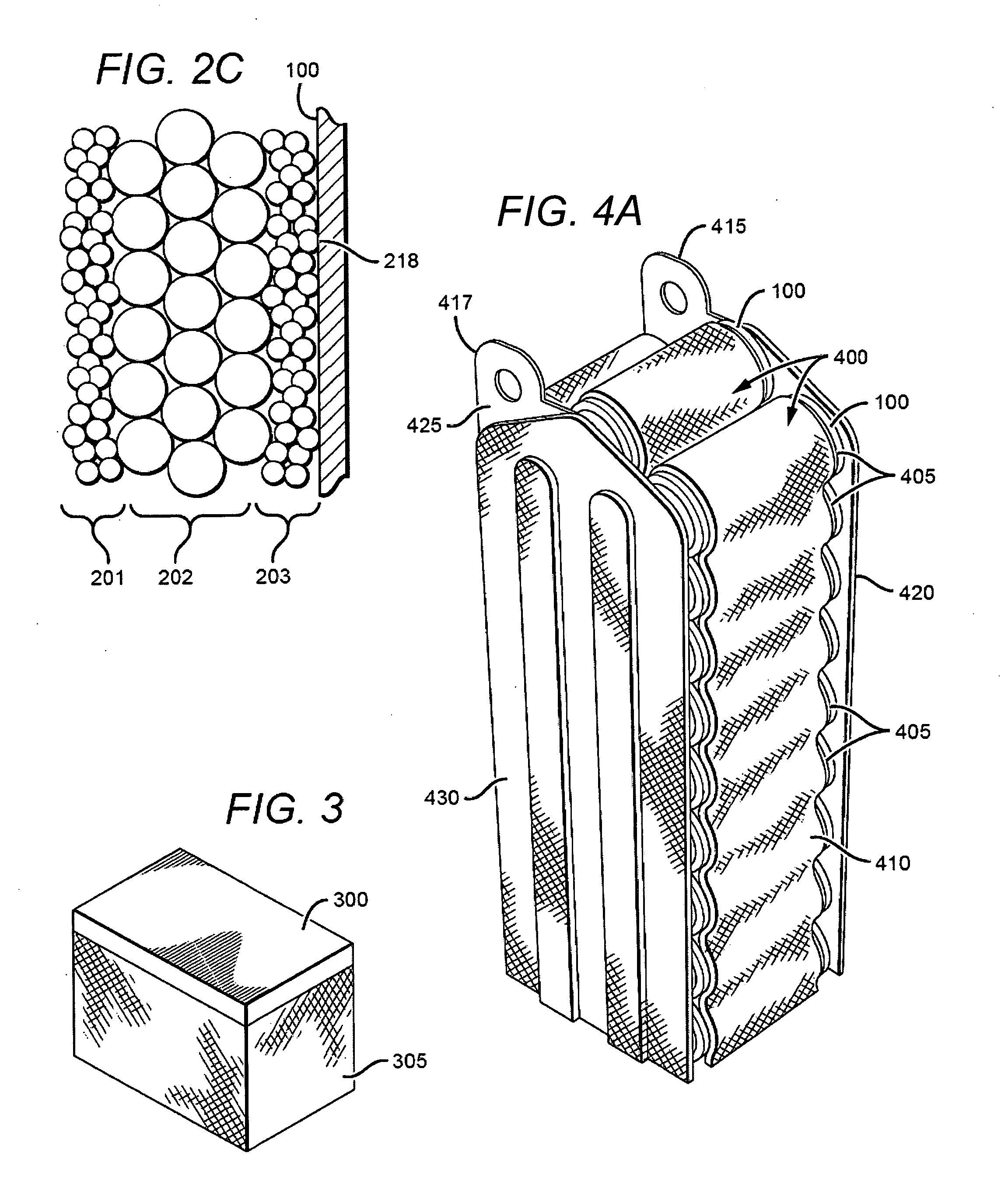
[0059]A cylindrical rechargeable 26650 LFP cell (26650) is covered using 250 microns thick non-woven porous structure on the cylindrical cell wall and placed inside a vapor-tight enclosure. The charge and discharge process of example 1 is repeated. The temperature rise during the discharge is shown in FIG. 10. The effect of the evaporation-condensation process inside the chamber reduces the temperature increase to only 3° C.
example 3
[0060]The experiment in example 1 is repeated except that the charge is carried at a constant current (CC) 4 Amp (1.5 C) charge until cell voltage reaches 3.65 V (approximately at ˜3000 s), and then constant voltage charge until current trickles down 65 mA. The ambient temperature is 60° C. The temperature of the cell is recorded as a function of time during the charge and the temperature peaks just after the constant current step at 11° C., as shown in FIG. 11.
Example 4
[0061]The cell is covered with a non-woven porous structure as in example 2 and the charge procedure of example 3 is followed. In this example, the temperature increase of the cell peaks at ˜2° C. (FIG. 11) demonstrating the dramatic effect of the cooling process provided by the addition of the porous wick.
[0062]FIG. 12 is a perspective view of one embodiment of a heat source that has an outer surface of its cell casing wall formed into parallel microchannels to establish a capillary void matrix. In FIG. 12, the cyli...
PUM
| Property | Measurement | Unit |
|---|---|---|
| boiling point | aaaaa | aaaaa |
| boiling point | aaaaa | aaaaa |
| temperature | aaaaa | aaaaa |
Abstract
Description
Claims
Application Information
 - R&D
- Intellectual Property
- Life Sciences
- Materials
- Tech Scout
- Unparalleled Data Quality
- Higher Quality Content
- 60% Fewer Hallucinations
Browse by: Latest US Patents, China's latest patents, Technical Efficacy Thesaurus, Application Domain, Technology Topic, Popular Technical Reports.
© 2025 PatSnap. All rights reserved.Legal|Privacy policy|Modern Slavery Act Transparency Statement|Sitemap|About US| Contact US: help@patsnap.com


