
A safety protection arrangement for a lighting arrangment

Active Publication Date: 2017-02-16
KONINKLJIJKE PHILIPS NV
View PDF2 Cites 2 Cited by
  • Summary
  • Abstract
  • Description
  • Claims
  • Application Information

AI Technical Summary

Benefits of technology

The patent describes a way to measure electrical parameters and compare them to expected values to create a fuse function. The driving settings may include turning the LEDs on or off to get better results. Turning off the LEDs makes them easier to detect short circuits. This technique helps to improve the reliability and efficiency of LEDs.

Problems solved by technology

When electrical wires are accidently shorted, a high current will flow locally.
Electrical fuses are not effective for some types of lighting system, for example lighting systems consisting of a large number of lights (such as LEDs) connected to form a large wired network.
As a consequence, the total current during normal operation can be similar to the total current in the case of a short, making it difficult to detect shorts.
For this reason, a regular fuse is not an effective safety feature.
Thus, for a system which is configurable in different ways, the required fuse current cannot easily be set.
This makes it difficult to limit the current through the system.
Electrical lighting circuits that are worn close to the body can present safety risks.
For example, when the electrical wiring or the LEDs fail, the power dissipation can locally increase.
This can result in local hot spots, which can harm the skin, or even ignite flames of the textile clothing.

Method used


Image

  • A safety protection arrangement for a lighting arrangment
  • A safety protection arrangement for a lighting arrangment
  • A safety protection arrangement for a lighting arrangment

Examples


first embodiment

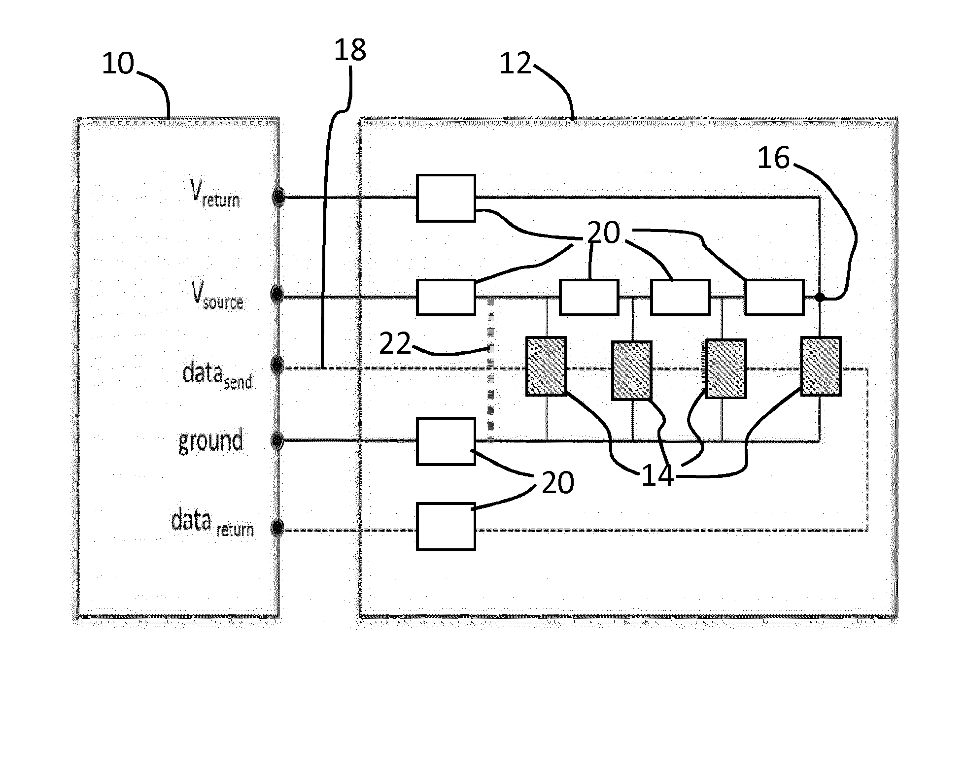
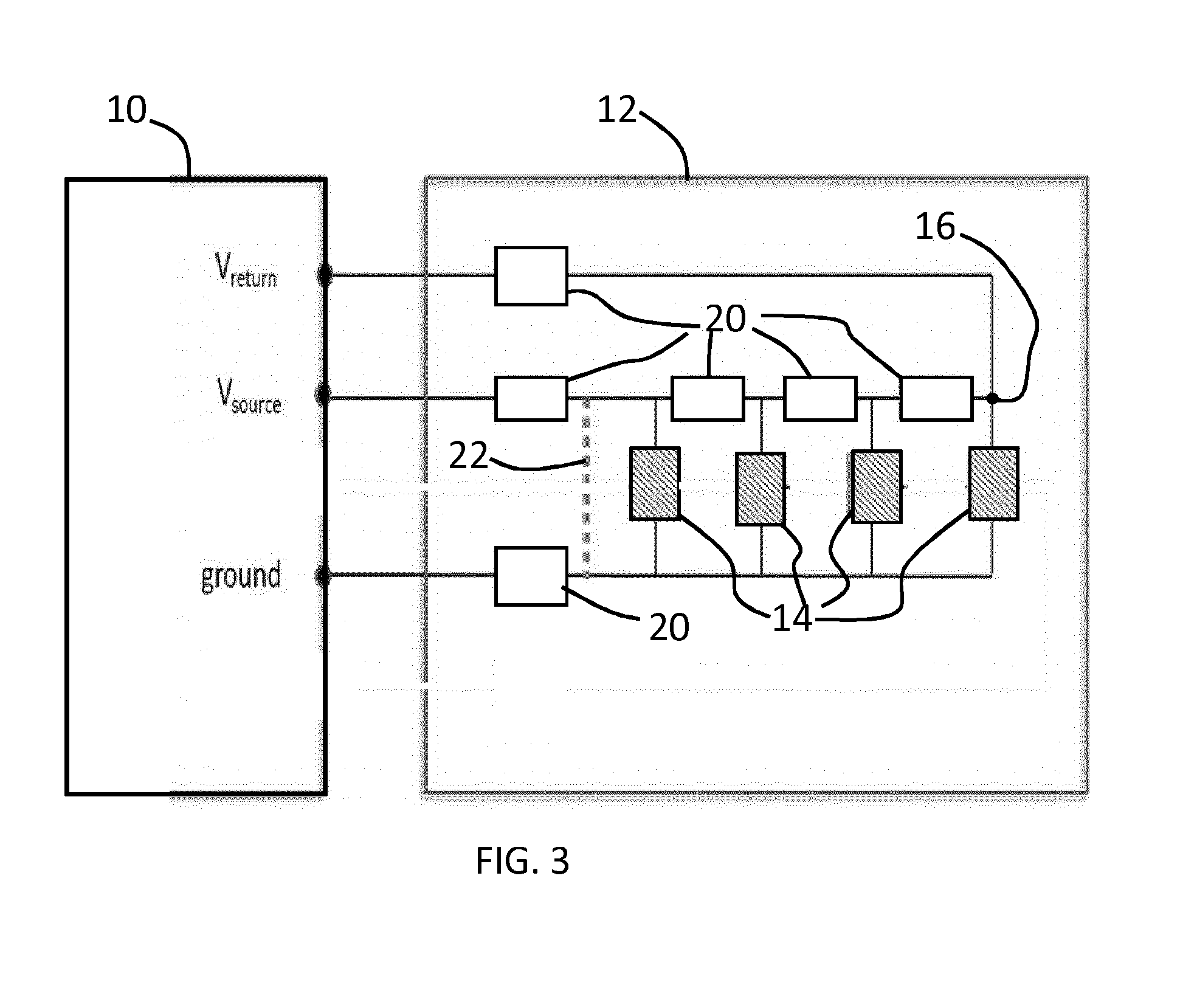
[0080]A first embodiment functions as a variable fuse. In this case, the current drawn from the supply is limited to a value that is estimated by taking into account the driving settings, such as the lighting arrangement configuration (in particular how many LEDs are turned ON) and the resistance of all the components and wires. The estimated current will vary over time for dynamic lighting systems, and the fuse current (maximum current) will also vary over time.

[0081]The current drawn can be measured based on the current flowing out of the Vsource pin, for example by monitoring the voltage across a resistor in series with the Vsource output.

second embodiment

[0082]A second embodiment is based on measuring the voltage drop over the voltage supply wire. By comparing the measured value with the estimated value, shorts can be easily detected.

third embodiment

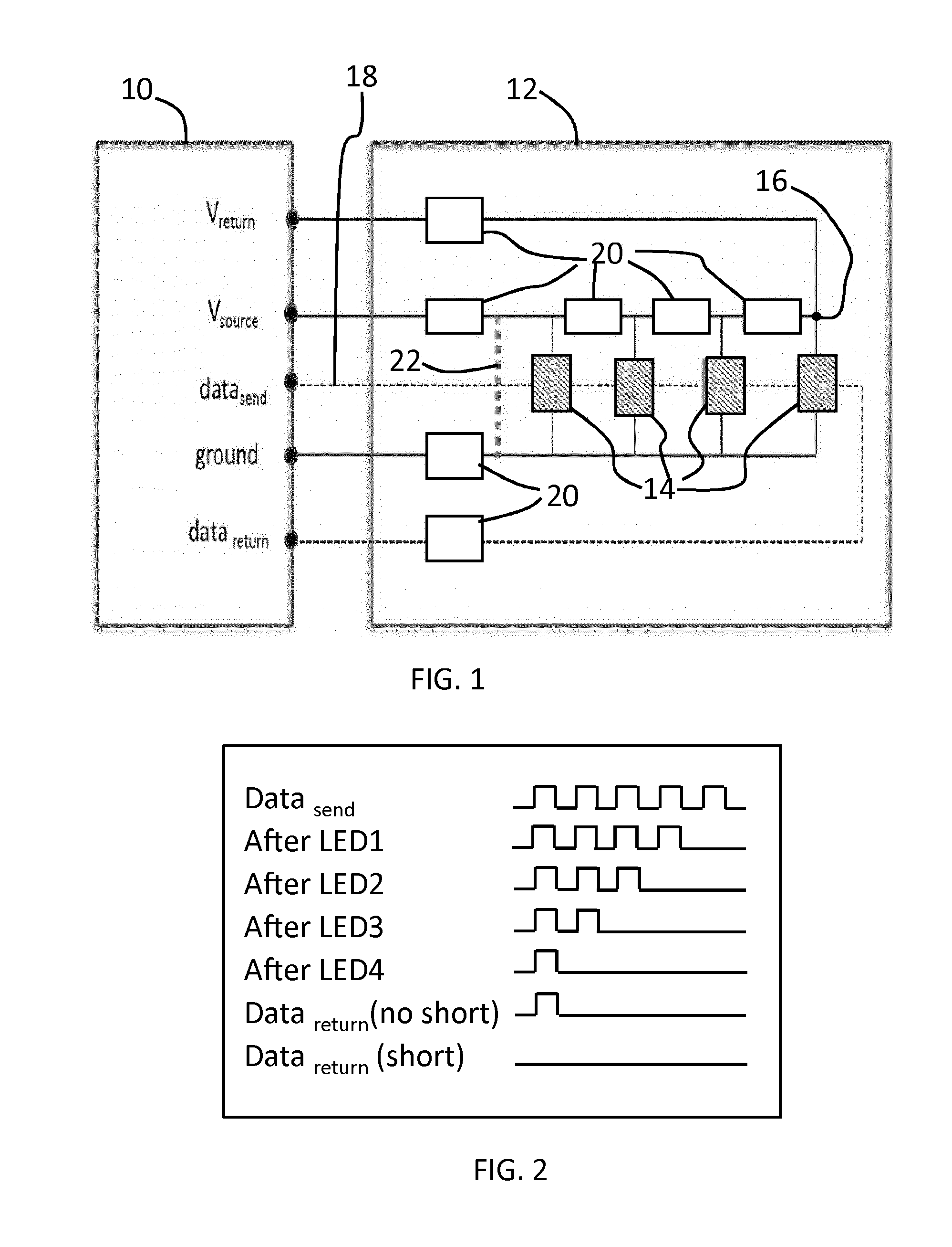
[0083]A third embodiment is based on measuring the data return signal and comparing it with estimated values. Failures in the LED package can affect the data signal going through the LEDs as explained above.


PUM


Abstract

A safety protection arrangement is provided for a lighting arrangement. An electrical parameter is measured with the driving of the lighting arrangement with particular driving settings and it is compared with an estimated expected value of the electrical parameter so that a safety warning signal or a shutdown can be provided in the event of a detected system failure.

Description

FIELD OF THE INVENTION[0001]The invention relates to lighting arrangements and in particular to safety protection devices for lighting arrangements, for example to provide a cut-off in the event of an electrical short circuit.BACKGROUND OF THE INVENTION[0002]To ensure a safe system, most electrical equipment is equipped with an electrical fuse. When electrical wires are accidently shorted, a high current will flow locally. This can be avoided by an electrical fuse, shutting down the system when the current becomes higher than the expected current during normal use.[0003]Electrical fuses are not effective for some types of lighting system, for example lighting systems consisting of a large number of lights (such as LEDs) connected to form a large wired network. Examples of this type of lighting systems are wearable lighting applications or sleeping bags equipped with lighting.[0004]There are two reasons why this type of lighting system requires a different safety system. First of all...

Claims


Application Information

Patent Timeline
IPC IPC(8): H05B33/08F21V25/10G01R31/44F21V33/00H05B44/00
CPCH05B33/089F21V33/0008F21Y2115/10H05B33/0845G01R31/44F21V25/10F21Y2101/00H05B45/58Y02B20/30H05B47/00H05B45/10
Inventor TROUWBORST, MARIUS LEENDERTCLOUT, RAMON ANTOINE WIROVAN OS, JACOBUS PETRUS JOHANNESKNEEPKENS, FRANCISCUS ANTONIUS
Owner KONINKLJIJKE PHILIPS NV
Learn More