Circuit assembly and electrical junction box

Active Publication Date: 2017-02-23
AUTONETWORKS TECH LTD +2
View PDF1 Cites 1 Cited by
  • Summary
  • Abstract
  • Description
  • Claims
  • Application Information

AI Technical Summary

Benefits of technology

The technique described in this patent text provides an adhesive sheet to cover the gap between adjacent busbars in a connection opening. This prevents the adhesive agent from getting into direct contact with the lower surface of the electronic component, reducing its impact on the performance of the component. As a result, a circuit assembly or an electrical junction box can be achieved with high connection reliability.

Problems solved by technology

However, these electronic components have a relatively large heat generation, and thus if heat generated by the electronic components stays in the case, there will be a risk that the temperature in the case increases and the performance of the electronic components accommodated in the case decreases.

Method used


Image

  • Circuit assembly and electrical junction box
  • Circuit assembly and electrical junction box
  • Circuit assembly and electrical junction box

Examples


Embodiment Construction

[0021]An embodiment will be described with reference to FIGS. 1 to 5.

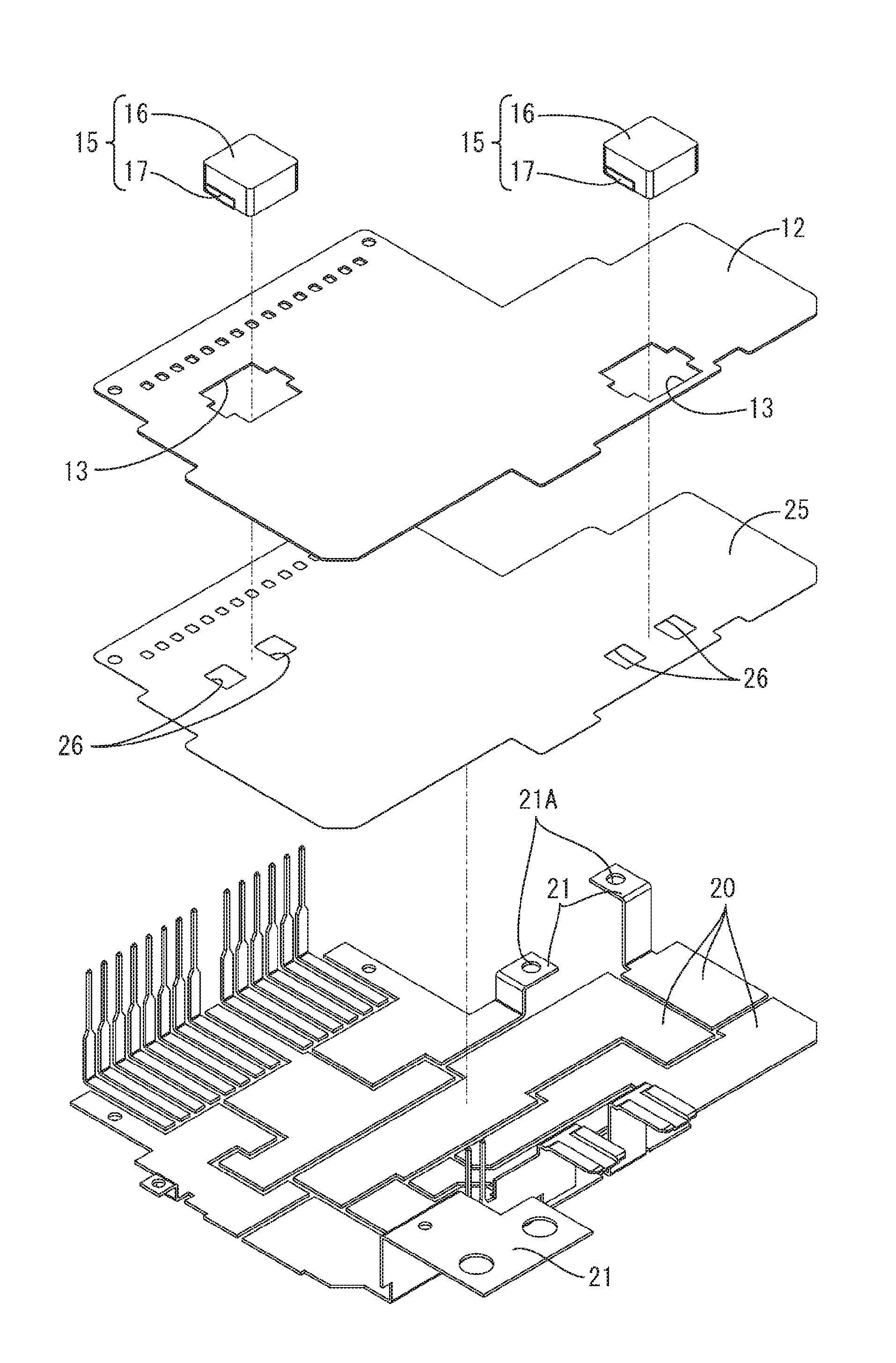
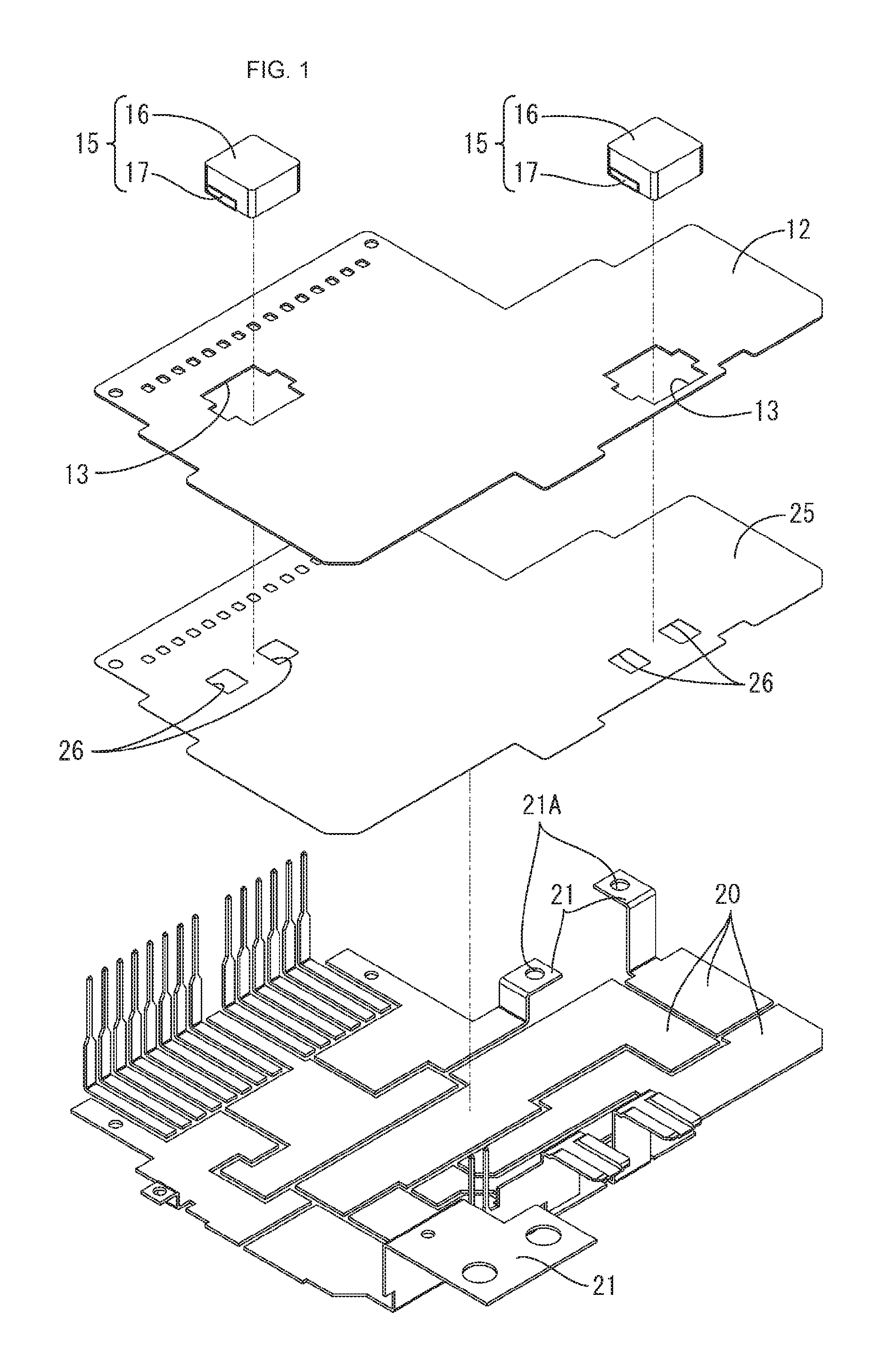
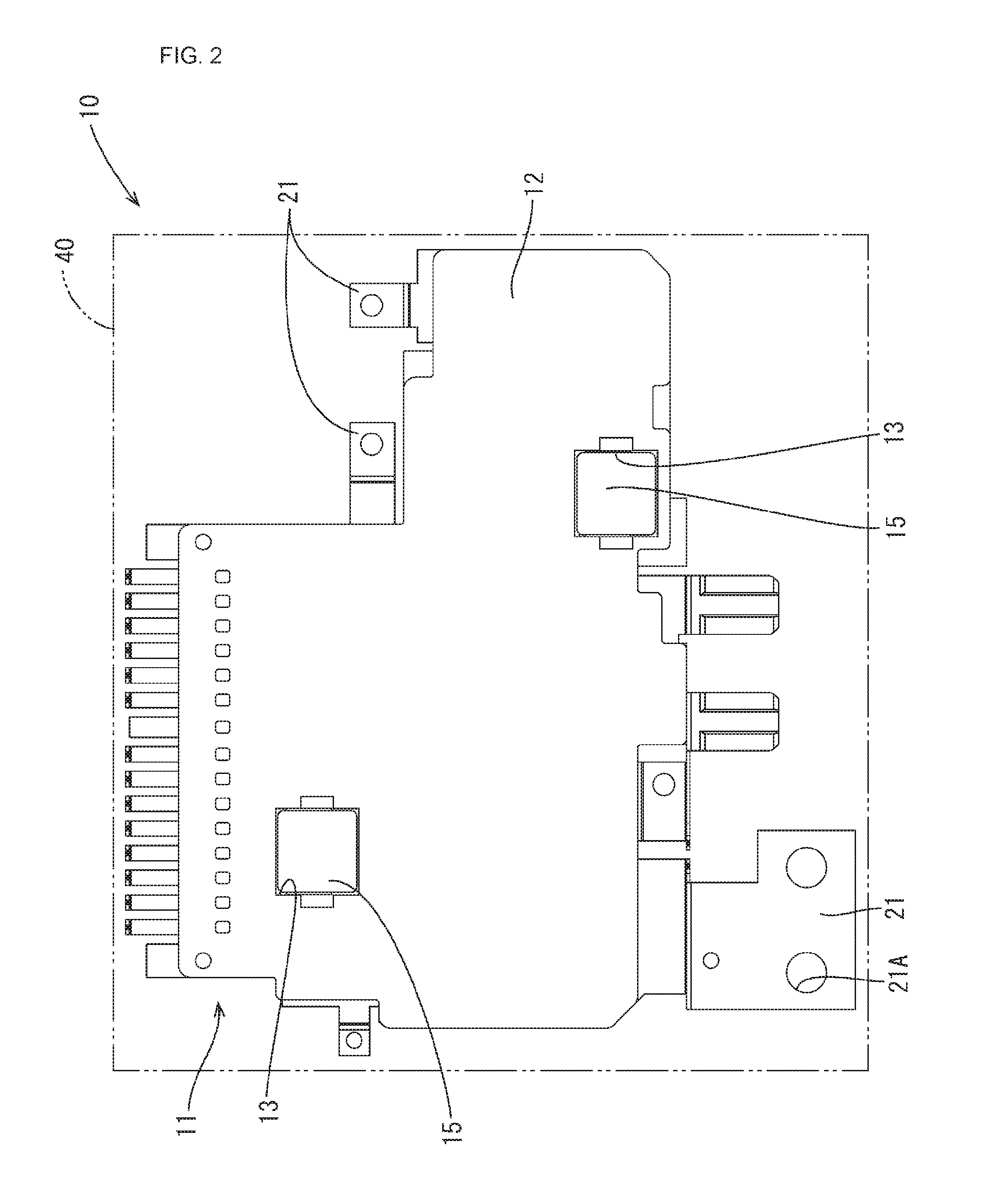
[0022]An electrical junction box 10 of the present embodiment is provided with a circuit assembly 11 including a circuit board 12 and a heatsink 30, and a synthetic resin case 40 that accommodates the circuit assembly 11. Note that in the following description, the upper side of FIG. 1 refers to “front side” or “upper side”, and the lower side of FIG. 1 refers to “rear side” or “lower side”.

[0023]As shown in FIG. 1, the circuit assembly 11 is provided with the circuit board 12, coils 15 (an example of electronic component) that are arranged on the front surface (upper side of FIG. 1) of the circuit board 12, a plurality of busbars 20 that are arranged on the rear surface (lower side of FIG. 1) of the circuit board 12, and the heatsink 30 (see FIG. 5) that is arranged on the rear surfaces of the busbars 20.

[0024]The circuit board 12 is substantially L-shaped, and has, on its front surface, a conductive circuit that ...


PUM


Abstract

Provided is a circuit assembly that includes a circuit board that has a connection opening, a plurality of busbars that are laminated on one surface side of the circuit board via an adhesive sheet, a coil that has a main portion and a plurality of lead terminals, the coil being arranged on the other surface side of the circuit board by the lead terminals being connected to the plurality of busbars that are exposed through the connection opening, and a heatsink that is laminated on a side of the plurality of busbars that is opposite to the circuit board via an adhesive agent. The adhesive sheet has sheet openings through which the plurality of busbars are exposed and the plurality of lead terminals are connected to the plurality of busbars, the adhesive sheet covering a gap between the plurality of busbars, the gap being located in the connection opening.

Description

CROSS-REFERENCE TO RELATED APPLICATIONS[0001]This application is the U.S. national phase of PCT / JP2015 / 062674 filed Apr. 27, 2015, which claims priority of Japanese Patent Application JP 2014-100258 filed May 14, 2014.FIELD OF THE INVENTION[0002]The technique disclosed in the present description relates to a circuit assembly, and an electrical junction box.BACKGROUND OF THE INVENTION[0003]Conventionally, devices in which a circuit assembly including a circuit board on which various electronic components are mounted is accommodated in a case are known as devices for energizing and de-energizing in-car electric components.[0004]In such devices, the electronic components mounted on the circuit board are small and have superior functionality.[0005]However, these electronic components have a relatively large heat generation, and thus if heat generated by the electronic components stays in the case, there will be a risk that the temperature in the case increases and the performance of the...

Claims


Application Information

Patent Timeline
IPC IPC(8): H02G3/16H05K1/18H05K7/06H05K1/02
CPCH02G3/16H05K1/0203H05K1/181H05K2201/1003H05K2201/10272H05K2201/10015H05K2201/10022H05K7/06H05K7/20854
Inventor KOBAYASHI, TAKEHITOSASAKI, YOSHIKAZUYAMANE, SHIGEKIOOI, TOMOHIROKITA, YUKINORI
Owner AUTONETWORKS TECH LTD
Why Eureka
Try Eureka