
Method and apparatus for purifying a gas containing pollutants

a technology of exhaust gas and purification method, which is applied in the direction of gas treatment, particle charging/ionising station, dispersed particle filtration, etc., can solve the problems of long time it takes to make the method operative, high fuel consumption, and lack of flexibility in case of failure to meet the requirements of the method

Inactive Publication Date: 2017-03-02
UGRA ALTERNATIVE ENERGY
View PDF0 Cites 1 Cited by
  • Summary
  • Abstract
  • Description
  • Claims
  • Application Information

AI Technical Summary

Benefits of technology

This patent introduces a method and apparatus for purifying gases containing pollutants. The invention has two main benefits. Firstly, it offers a cheaper and more efficient way to handle these gases compared to current methods. Secondly, it provides a simple and easy-to-use solution that is affordable and can overcome the limitations of current technology.

Problems solved by technology

This known gas purification method does however have a number of drawbacks, tied in particular to the high consumption of fuel, to the presence of partially oxidized components in the exiting fumes, to the long time it takes to make the method operative and to the lack of flexibility in case of variable load conditions.
A further drawback also regards the cleaning and disposal of these electro-filters and their waste product.
This type of equipment however has large overall dimensions and requires high investment, running and maintenance costs.

Method used


Image

  • Method and apparatus for purifying a gas containing pollutants
  • Method and apparatus for purifying a gas containing pollutants

Examples


Embodiment Construction

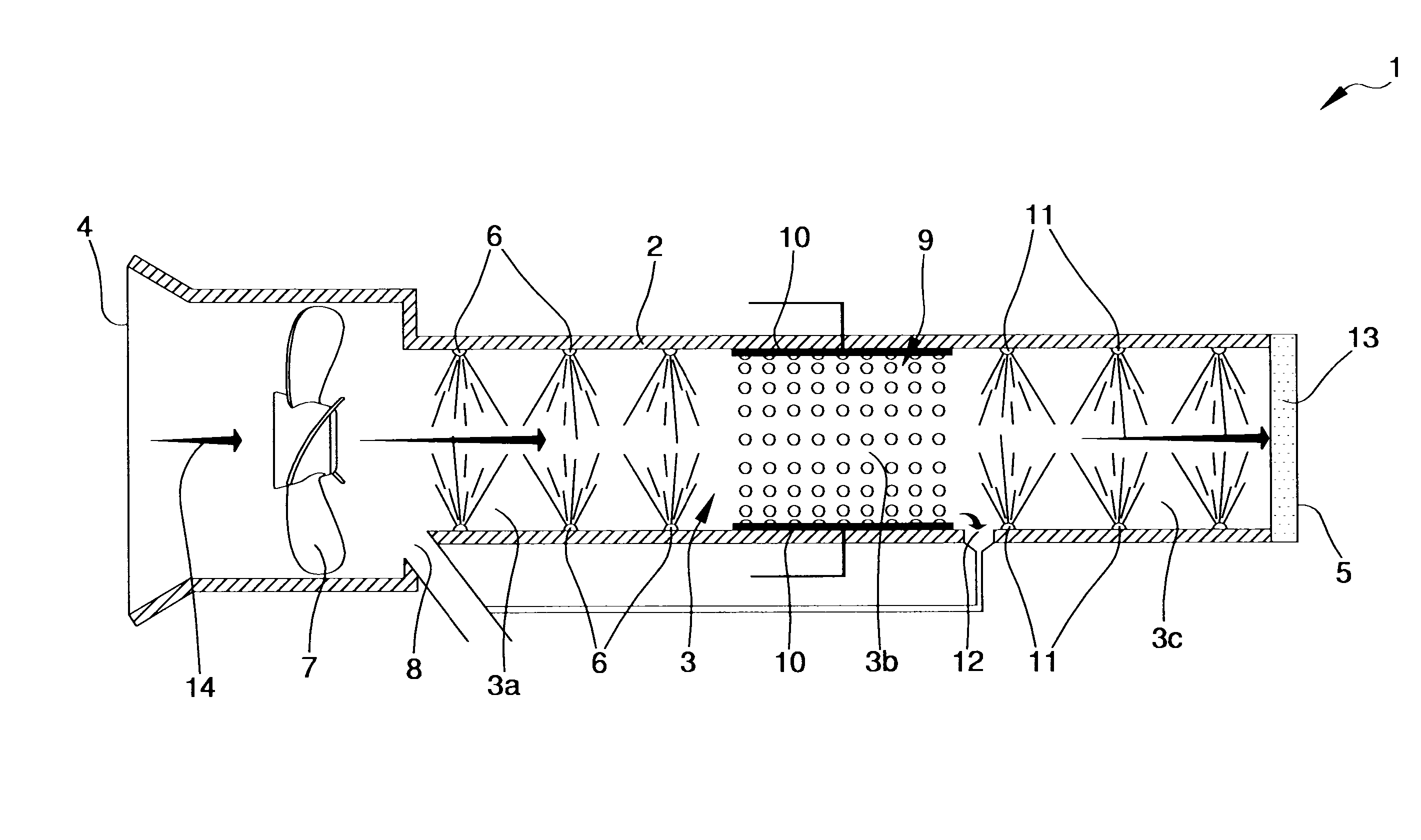
[0011]The main aim of the present invention is to provide a method and an apparatus for the purification of gases which permits successfully abating the pollutants, both organic and inorganic, contained in the treated gas.

[0012]Within this aim, an object of the present invention is to provide a method and an apparatus for the purification of gases containing pollutants having low investment, operating and maintenance costs compared to the methods and equipment of known type currently used.

[0013]Another object of the present invention is to provide a method and an apparatus for the purification of gases containing pollutants which allow to overcome the mentioned drawbacks of the prior art within the ambit of a simple, rational, easy, effective to use as well as affordable solution.

[0014]The above mentioned objects are achieved by the present method having the characteristics of claim 1.

[0015]The above mentioned objects are achieved by the present apparatus having the characteristics ...


PUM

PropertyMeasurementUnit
Currentaaaaaaaaaa
Currentaaaaaaaaaa
Electric potential / voltageaaaaaaaaaa

Abstract

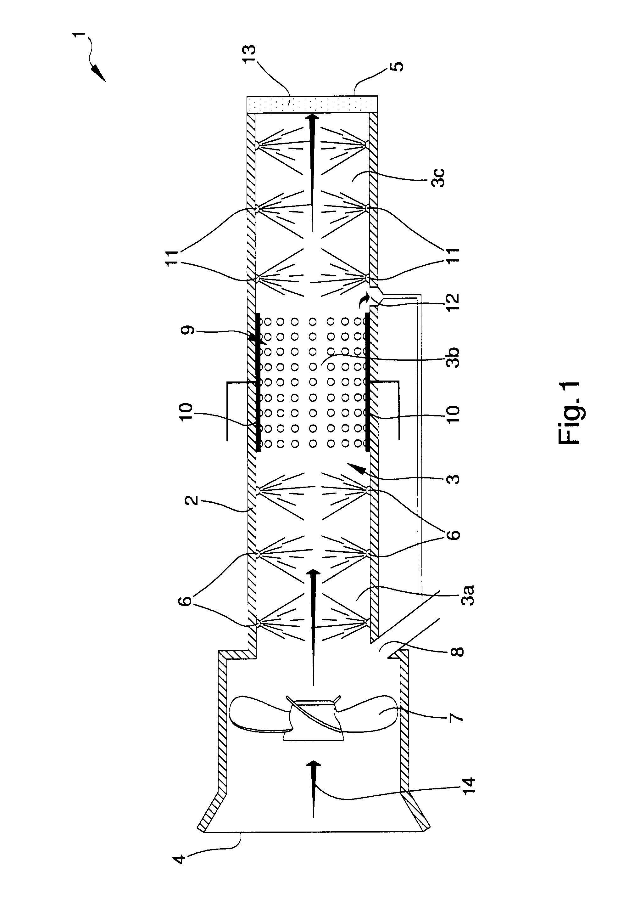
The method for the purification of a gas containing pollutants, particularly fumes, comprising the following steps of:providing a purification apparatus comprising a hollow body defining a purification chamber;feeding of a gas to be purified inside the purification chamber;first dispensing operation of nebulized water inside a first portion of the purification chamber to intercept the gas to be purified for the abatement of the organic and / or inorganic compounds present in the gas itself;treatment of the gas coming out of the first portion in a second portion arranged downstream of the first portion in the direction of gas flow;second dispensing operation of nebulized water inside a third portion of the purification chamber, arranged downstream of the second portion in the direction of gas flow;where nebulized water comprises deuterium and where the treatment comprises the formation of electric discharges in the second portion to ionize the gas coming out of the first portion and to obtain a state of plasma, the formation of electric discharges taking place between at least a pair of electrodes arranged inside the second portion and powered with a pulsating direct current having a voltage between 24,000 volts and 28,000 volts and an amperage between 0.1 A and 1.5 A and being able to cause the molecular dissociation of the organic compounds present in the gas to be purified.

Description

TECHNICAL FIELD[0001]The present invention relates to a method and an apparatus for the purification of exhaust gases containing pollutants, particularly fumes.BACKGROUND ART[0002]As is known, the need continues to be very much felt to treat gas containing pollutants such as, e.g., the fumes from combustion plants or the wastewaters from industrial processes containing both organic and inorganic pollutants, such as particulate and heavy metals.[0003]Equally important, from both an economic and environmental viewpoint, is the abatement of the CO2 contained in the above exhaust gases.[0004]For obvious environmental reasons, such pollutants must be disposed of before the gas is emitted into the atmosphere.[0005]In the case of gas containing mainly organic pollutants, the purification process is generally performed by means of combustion.[0006]More in detail, the gas is introduced into a combustion chamber containing a flame suitably kept alight by a fuel and within which waste product ...

Claims


Application Information

Patent Timeline
IPC IPC(8): B01D53/32B01D46/00B01D53/78B01D53/38B01D53/62
CPCB01D53/32B01D53/38B01D53/62B01D53/78B01D2258/02B01D2259/818B01D2252/103B01D2257/504B01D2258/0283B01D46/0027B01D2257/70B03C3/38Y02C20/40
Inventor FABBRI, MARIO
Owner UGRA ALTERNATIVE ENERGY
Learn More