Coater apparatus and method for additive manufacturing

a powder coating and additive manufacturing technology, applied in the direction of additive manufacturing processes, manufacturing tools, and layer means, etc., can solve the problems of limited additive manufacturing, waste of powder, and limited process flexibility

Active Publication Date: 2017-03-02
GENERAL ELECTRIC CO
View PDF14 Cites 29 Cited by
  • Summary
  • Abstract
  • Description
  • Claims
  • Application Information

AI Technical Summary

Problems solved by technology

Unlike casting processes, additive manufacturing is limited only by the position resolution of the machine and not limited by requ...

Method used


Image

  • Coater apparatus and method for additive manufacturing
  • Coater apparatus and method for additive manufacturing
  • Coater apparatus and method for additive manufacturing

Examples


Embodiment Construction

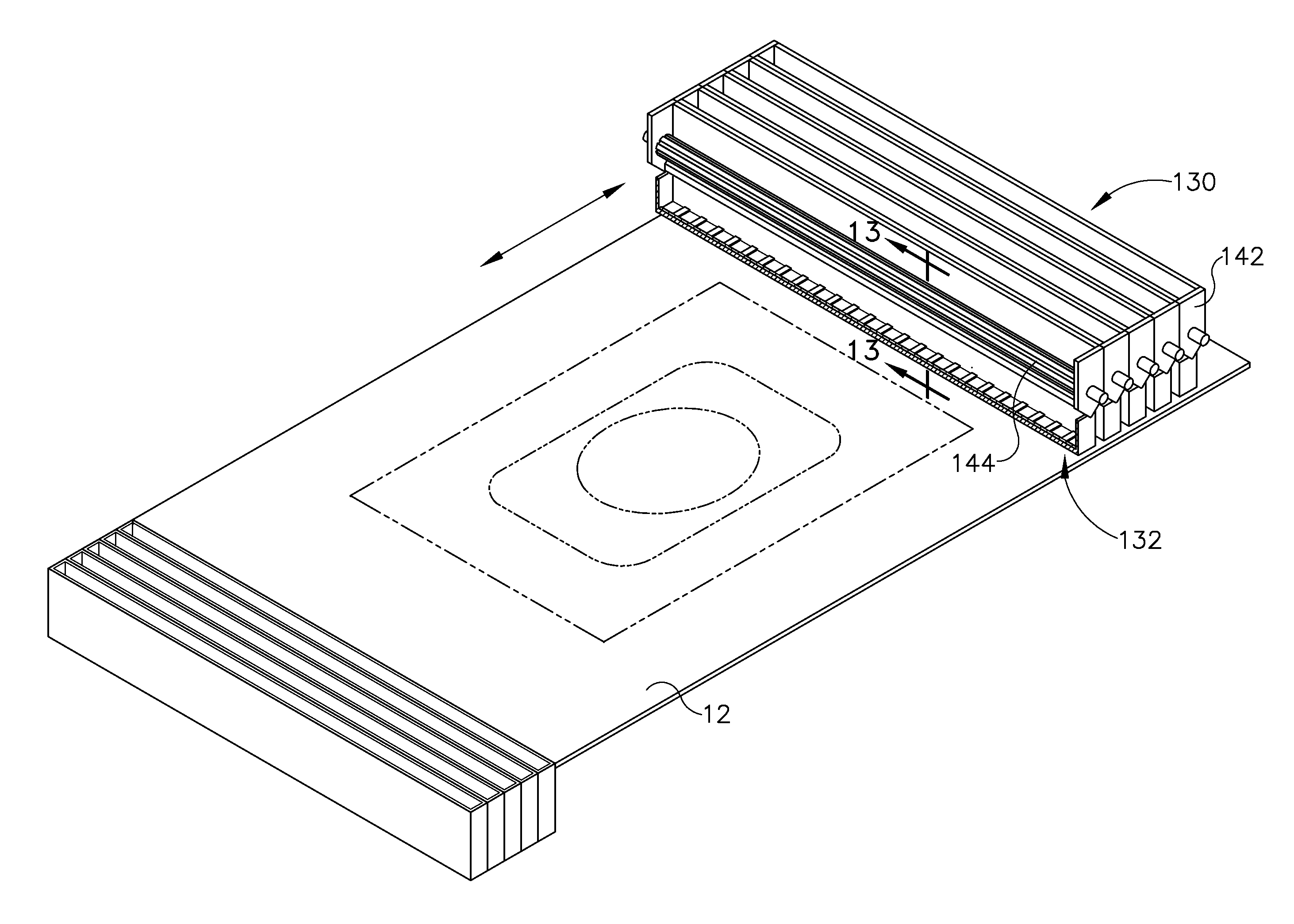
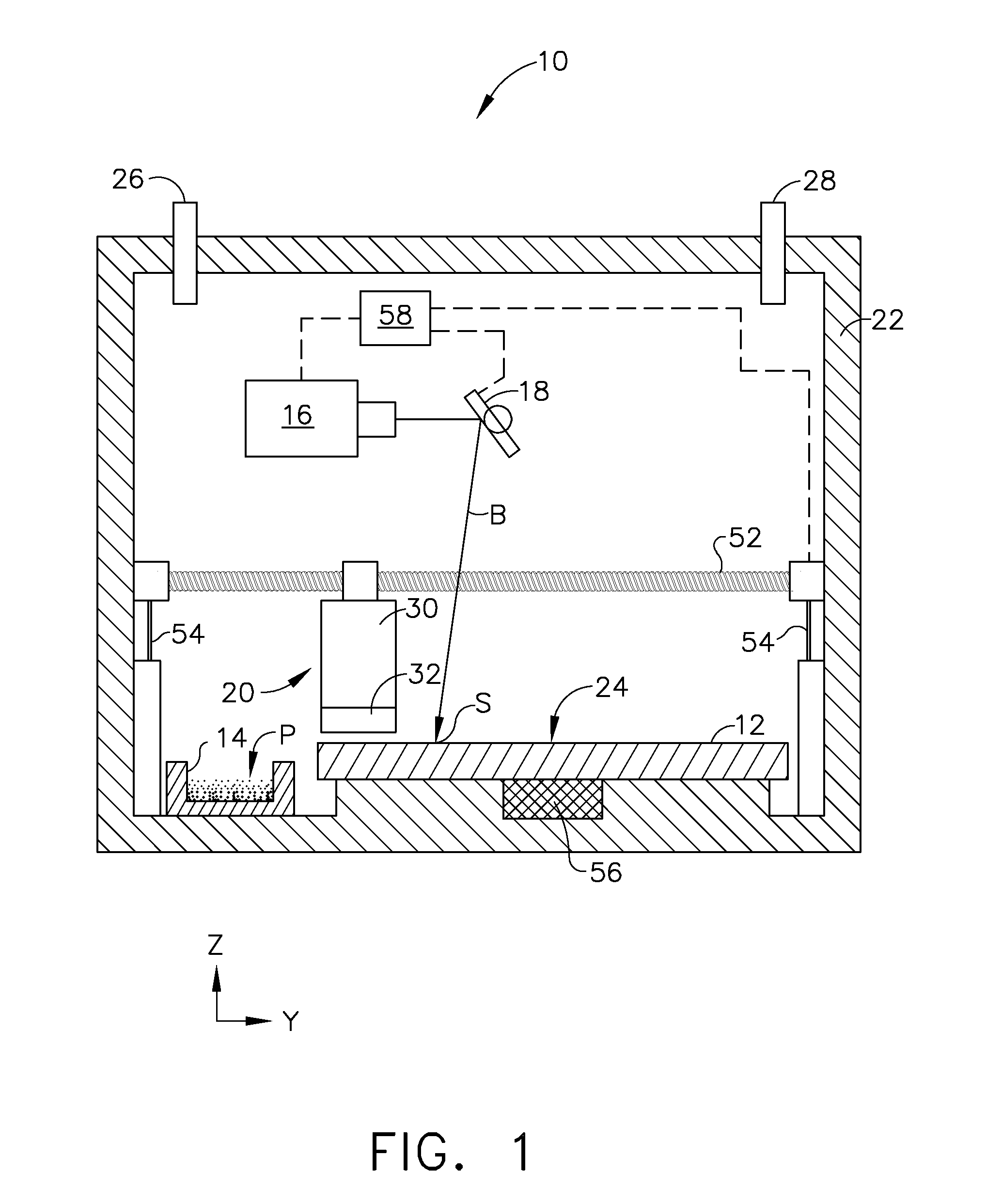
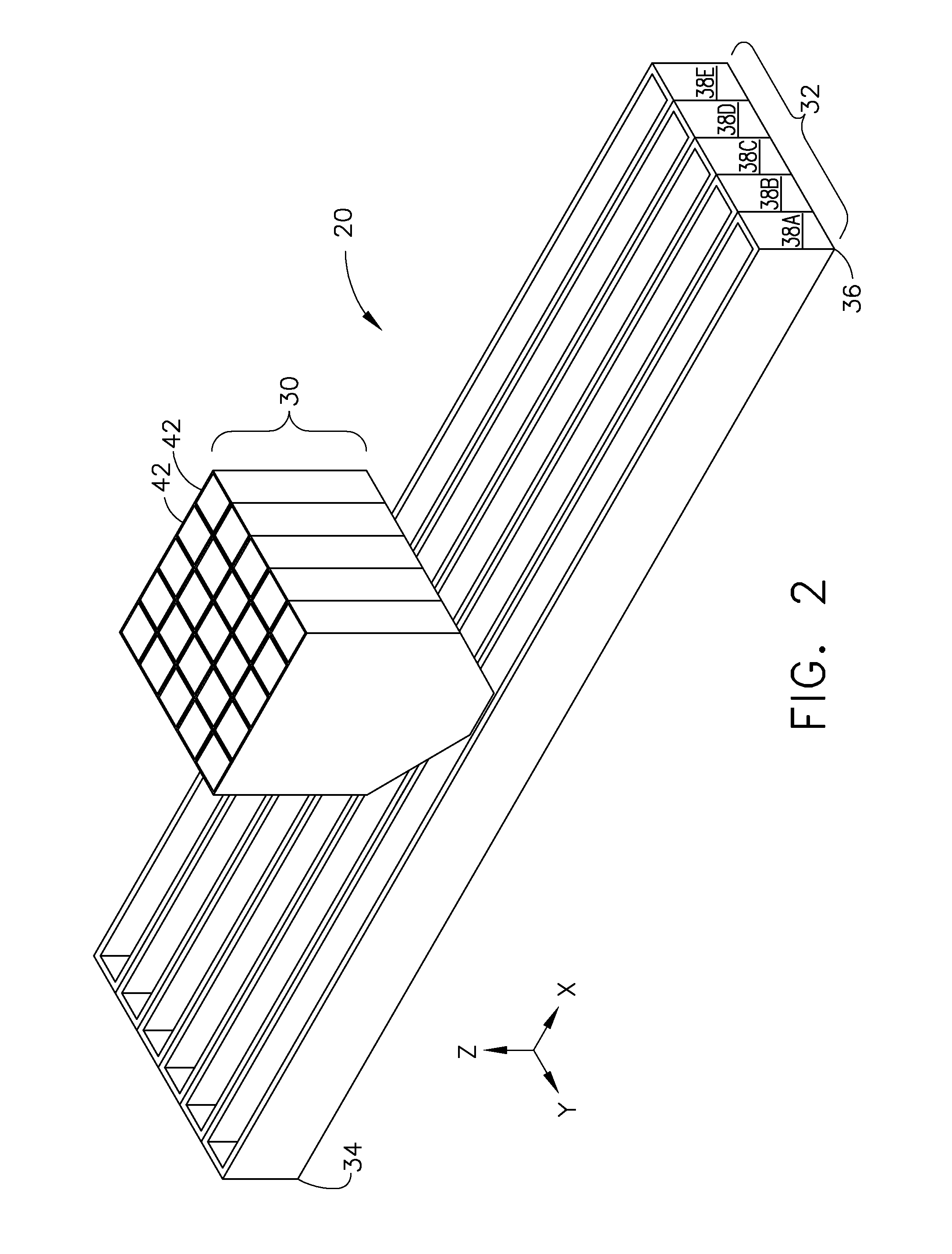
[0018]Referring to the drawings wherein identical reference numerals denote the same FIG. 1 illustrates schematically an exemplary additive manufacturing apparatus 10 suitable for carrying out an additive manufacturing process. The apparatus 10 may include a build platform 12, an excess powder container 14, a directed energy source 16, a beam steering apparatus 18, and a coater 20, all of which may be enclosed in a housing 22. Each of these components will be described in more detail below. In describing the apparatus 10, reference may be made to a system of three mutually perpendicular axes labeled X, Y, and Z as seen in FIGS. 1 and 2. This coordinate system is used merely for convenience and does not imply that any particular orientation of the apparatus 10 is required for operation.

[0019]The build platform 12 is a rigid structure providing a planar worksurface 24. The excess powder container 14 is an open-topped vessel which lies adjacent to the build platform 12, and serves as a...


PUM


Abstract

An additive manufacturing apparatus includes: a coater including: at least one trough including a plurality of side-by-side deposition valves.

Description

BACKGROUND OF THE INVENTION[0001]The present invention relates generally to additive manufacturing, and more particularly to apparatus and methods for additive manufacturing using a powder coater.[0002]Additive manufacturing is a process in which material is built up layer-by-layer to form a component. Unlike casting processes, additive manufacturing is limited only by the position resolution of the machine and not limited by requirements for providing draft angles, avoiding overhangs, etc. as required by casting. Additive manufacturing is also referred to by terms such as “layered manufacturing,”“reverse machining,”“direct metal laser melting” (DMLM), and “3-D printing.” Such terms are treated as synonyms for purposes of the present invention.[0003]A known type of additive manufacturing process involves depositing powdered material onto a worksurface and then fusing the powder using radiant energy. This type of process often requires a large bulk of powder provided as a bed or appl...

Claims


Application Information

Patent Timeline
IPC IPC(8): B23K26/342B23K15/00
CPCB23K26/342B33Y10/00B33Y30/00B23K15/0086B29C64/153B29C64/20B22F10/00B22F12/57B22F10/28B22F12/55B22F12/50B22F10/73B29C64/329B29C64/255B29C64/205Y02P10/25
Inventor GILLESPIE, SHANE MATTHEWSTEVENSON, CHRISTIAN XAVIERKENNEY, PATRICK MICHAELWANG, PING
Owner GENERAL ELECTRIC CO
Why Eureka
Try Eureka