
Integrated air and vapor cycle cooling system

a cooling system and air vapor cycle technology, applied in the field of cooling systems, can solve the problems of higher power requirements and heat rejection demands, less efficient acs than vcs, and even greater challenges in the thermal management of these advanced systems

Active Publication Date: 2017-03-02
HONEYWELL INT INC
View PDF35 Cites 21 Cited by
  • Summary
  • Abstract
  • Description
  • Claims
  • Application Information

AI Technical Summary

Benefits of technology

This patent describes a cooling system for gas turbine engines that includes a turbo-compressor, a condenser, an evaporator, and a chilled fluid reservoir. The system uses high-pressure air from a turbo-fan engine or low-temperature air from an air cycle system (ACS) turbine to cool the engine. The invention also incorporates a vapor cycle system (VCS) refrigerant compressor and a magnetically coupled ACS turbine to achieve more efficient cooling. The technical effects of this invention include improved engine performance, reduced fuel consumption, and increased operational range.

Problems solved by technology

While these power demands are significant, thermal management of these advanced systems will present an even greater challenge, due to low component efficiencies and waste heat quality.
Low-observability requirements, such as limitations on ram air availability, composite aircraft skins which inhibit heat transfer, and higher efficiency engines with less fuel flow available for cooling, further compound this challenge.
However, ACS are much less efficient than VCS, resulting in higher power requirements and higher heat rejection demands.
On the other hand, VCS systems are more efficient, but require lower heat sink temperatures that are often not available without a dedicated ram air source, which still may be too hot to use during high speed flight.
Further, for the large thermal loads anticipated, the cooling system itself will require substantial power to drive it.
The use of electric power would further tax the vehicle's electric power generation capability and the power conditioning, motor controllers, and motors needed would be relatively heavy, expensive, and unreliable.
A direct mechanical drive may also be problematic as engines are not currently equipped for such high power take-off shaft loads, and incorporating such into new engine designs involves a number of design compromises including added weight, cost and mechanical complexity.

Method used


Image

  • Integrated air and vapor cycle cooling system
  • Integrated air and vapor cycle cooling system
  • Integrated air and vapor cycle cooling system

Examples


Embodiment Construction

[0015]The following detailed description is of the best currently contemplated modes of carrying out exemplary embodiments of the invention. The description is not to be taken in a limiting sense, but is made merely for the purpose of illustrating the general principles of the invention, since the scope of the invention is best defined by the appended claims.

[0016]Various inventive features are described below that can each be used independently of one another or in combination with other features. However, any single inventive feature may not address any of the problems discussed above or may only address one of the problems discussed above. Further, one or more of the problems discussed above may not be fully addressed by any of the features described below.

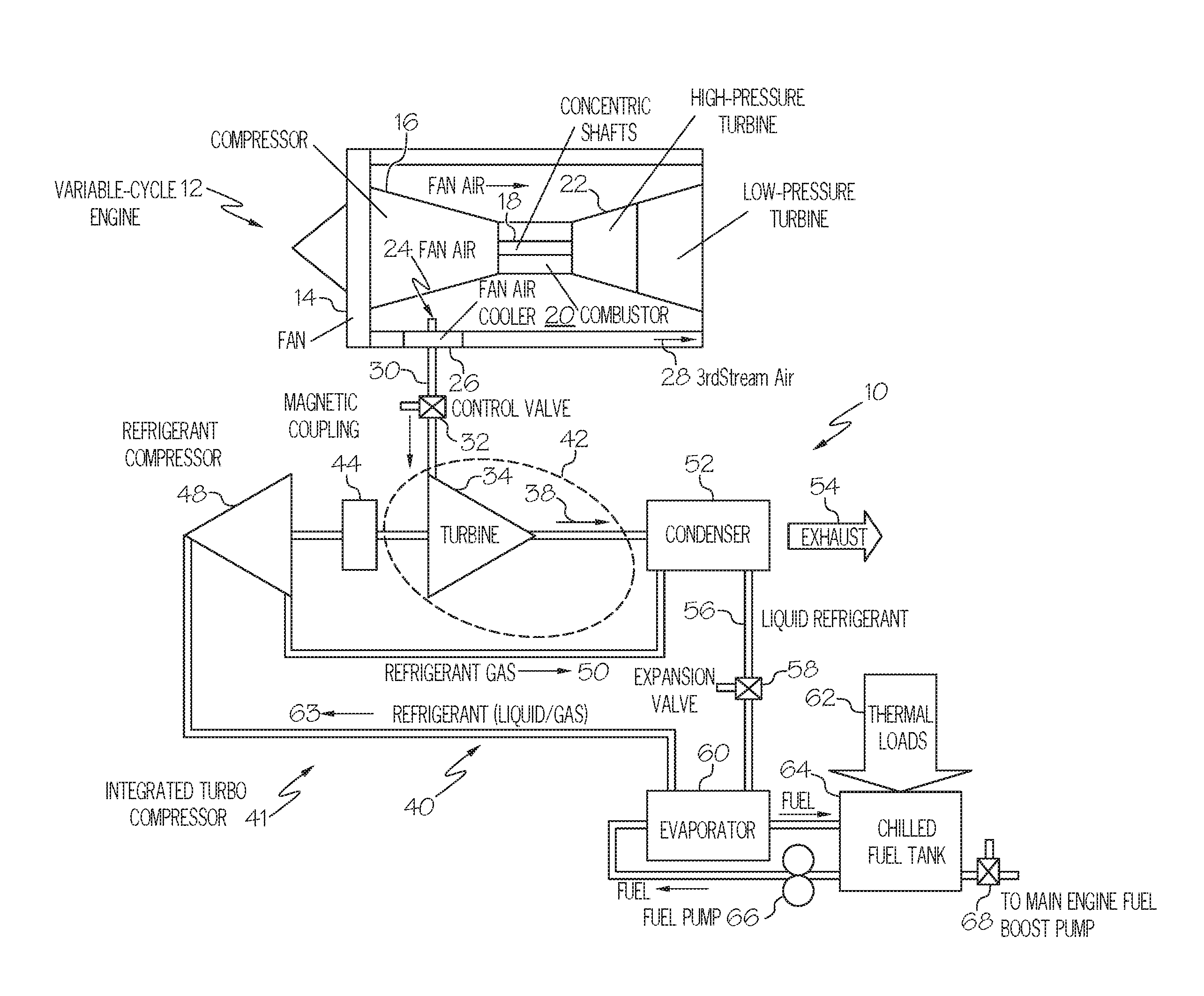
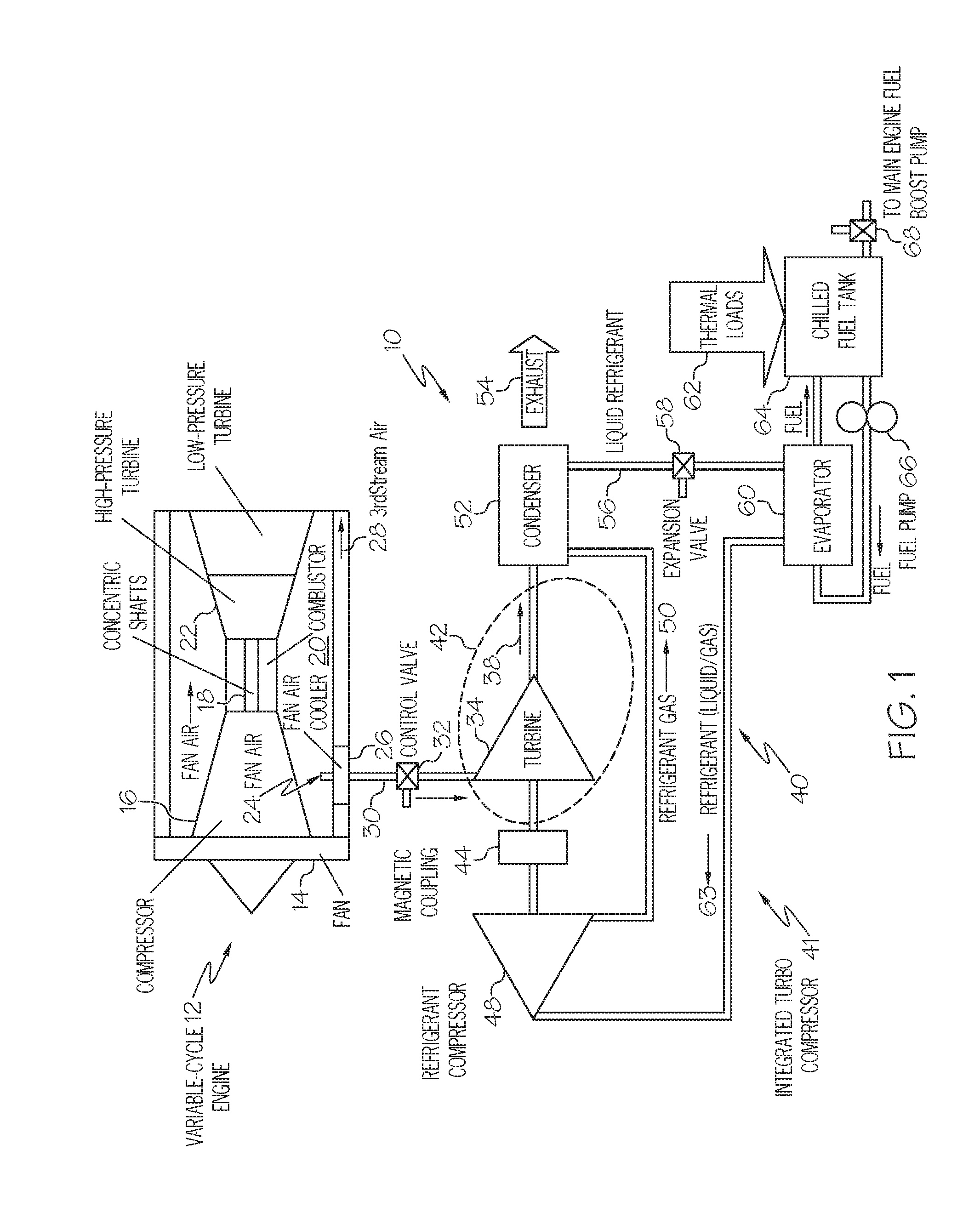
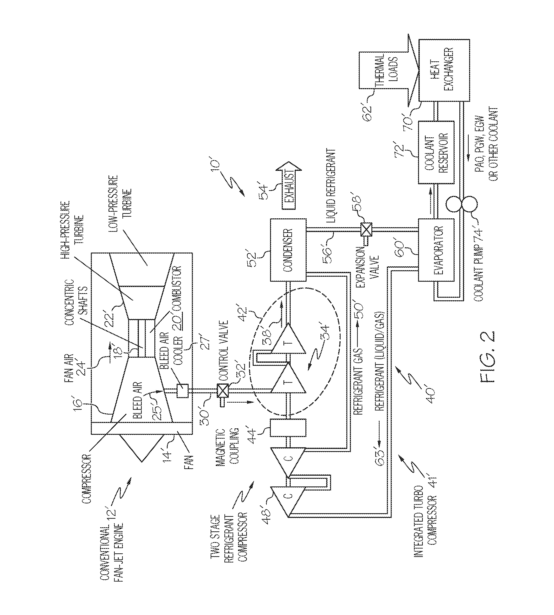
[0017]Generally, the present invention provides a hybrid air cycle system with a vapor cycle system by combining an ACS turbine and VCS compressor as part of a single turbo-compressor. A “simple-cycle” ACS, with cooled engine f...


PUM


Abstract

A cooling system in which an ACS (air cycle system) turbine may be driven by high pressure air from a turbo-fan engine and a VCS (vapor cycle system) having an evaporator and a VCS refrigerant compressor may be driven by the ACS turbine. Fluid of the chilled fluid reservoir, which may be chilled fuel, may be circulated through and cooled in the evaporator. In some embodiments, the ACS turbine may be coupled to the VCS refrigerant compressor by a magnetic coupling.

Description

RELATED APPLICATIONS[0001]The present application claims benefit of U.S. Provisional Application No. 62 / 212,201 filed Aug. 31, 2015.BACKGROUND OF THE INVENTION[0002]The present invention generally relates to cooling systems, and more particularly to systems that include both air and vapor cycle cooling systems.[0003]Future military aircraft will require greatly advanced capabilities in order to ensure air superiority, survival in heavily defended airspace, and success against a wide range of potential targets. These capabilities, including electronic attack and directed energy weapons, are expected to require as much as 10 times higher electric power levels than existing weapon systems.[0004]While these power demands are significant, thermal management of these advanced systems will present an even greater challenge, due to low component efficiencies and waste heat quality. Low-observability requirements, such as limitations on ram air availability, composite aircraft skins which in...

Claims


Application Information

Patent Timeline
Patent Type & Authority Applications(United States)
IPC IPC(8): B64D13/06B64D37/34
CPCB64D13/06B64D2013/0618B64D37/34B64D2013/0659B64D2013/0674Y02T50/50F25B25/005B64D2013/064B64D2013/0648B64D13/08
Inventor KOERNER, MIKEMACKNIGHT, ALLENNIKBIN, SIAMAKQUAN, MYRONROBLES, DANIEL R.
Owner HONEYWELL INT INC
Learn More