System and method for mitigating ice throw from a wind turbine rotor blade

a technology of wind turbine rotor blade and ice throw, which is applied in the direction of wind motors, wind motor control, motors, etc., can solve the problems of significant damage to the wind turbine, structural damage, and ice throw, and achieve optimal pitch angle, optimal stall margin, and the effect of reducing the damag

Inactive Publication Date: 2017-03-02
GENERAL ELECTRIC CO
View PDF6 Cites 31 Cited by
  • Summary
  • Abstract
  • Description
  • Claims
  • Application Information

AI Technical Summary

Benefits of technology

[0009]In one embodiment, the step of determining at least one of the power set point or the speed set point for the wind turbine based on the yaw position may further include: determining at least one sector for the yaw position, determining if the sector corresponds to one or more predetermined risk sectors, and reducing at least one of the power set point or the speed set point of the wind turbine if the sector corresponds to one of the predetermined risk sectors. In another embodiment, the method may also include maintaining the power set point and the speed set point of the wind turbine, reducing at least one of the power set point or the speed set point of the wind turbine, or increasing the power set point and the speed set point of the wind turbine so as to maximize power production.

Problems solved by technology

As the ice layer accumulating on a rotor blade becomes increasingly thicker, the aerodynamic surface of the blade is modified, thereby resulting in diminished aerodynamic performance.
Moreover, ice accumulation significantly increases the weight of a rotor blade, which can lead to structural damage as an increased amount of bending moments and / or other rotational forces act on the rotor blade.
Further, when there is a difference in the amount of ice accumulating on each of the rotor blades, a mass imbalance may occur that can cause significant damage to a wind turbine.
In addition, ice accumulation may be shed or throw from the turbine due to both gravity and / or mechanical forces of the rotating blades.
For example, an increase in ambient temperature, wind, and / or solar radiation may cause sheets or fragments of ice to loosen and fall, making the area directly under the rotor subject to the greatest risks.
Further, rotating turbine blades may throw or propel ice fragments some distance from the turbine, e.g. up to several hundred meters if conditions are right.
Falling ice may cause damage to neighboring structures and / or vehicles, as well as injury to site personnel and / or the general public, unless adequate measures are put in place for protection.
Due to the disadvantages associated with ice accumulation, a wind turbine may be shutdown when it is believed that ice has accumulated on the surface of one or more of the rotor blades.
Shutting down the wind turbine, however, is not desirable as this impacts power production.

Method used


Image

  • System and method for mitigating ice throw from a wind turbine rotor blade
  • System and method for mitigating ice throw from a wind turbine rotor blade
  • System and method for mitigating ice throw from a wind turbine rotor blade

Examples


Embodiment Construction

[0025]Reference now will be made in detail to embodiments of the invention, one or more examples of which are illustrated in the drawings. Each example is provided by way of explanation of the invention, not limitation of the invention. In fact, it will be apparent to those skilled in the art that various modifications and variations can be made in the present invention without departing from the scope or spirit of the invention. For instance, features illustrated or described as part of one embodiment can be used with another embodiment to yield a still further embodiment. Thus, it is intended that the present invention covers such modifications and variations as come within the scope of the appended claims and their equivalents.

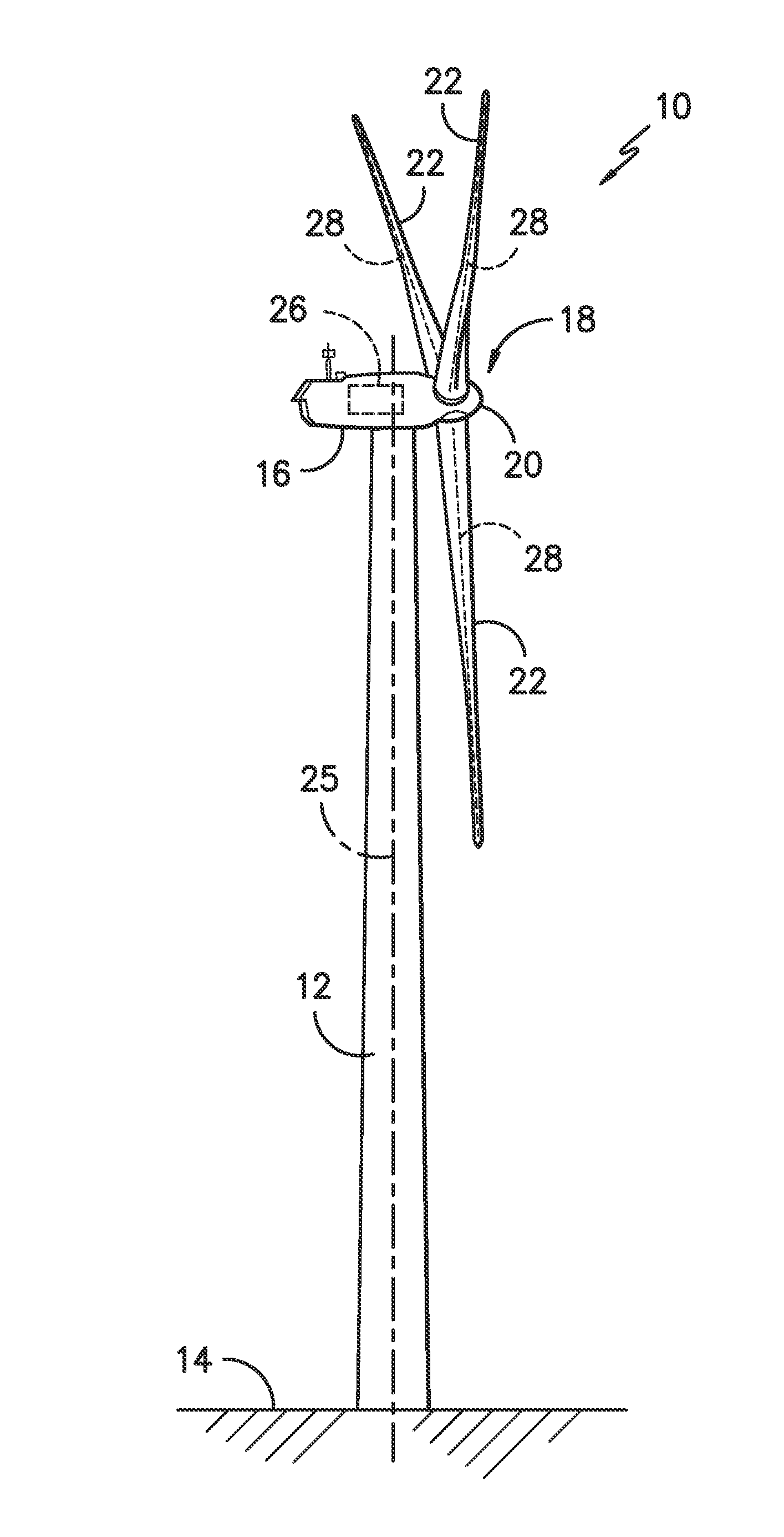
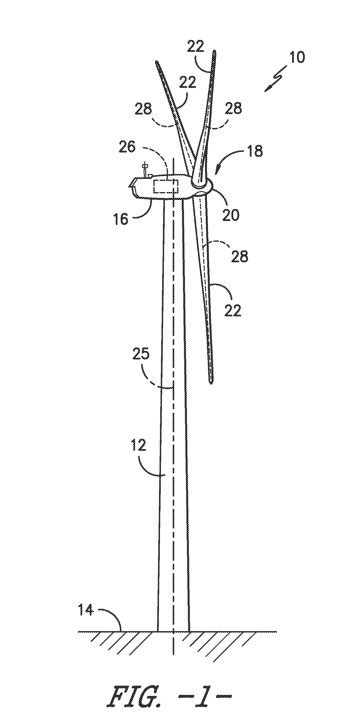
[0026]Generally, the present disclosure is directed to a system and method for mitigating ice throw from a rotor blade of a wind turbine during operation. Specifically, the present disclosure provides a controller configured to implement an ice protection c...


PUM


Abstract

The present disclosure is directed to a system and method for mitigating ice throw from one or more rotor blades of a wind turbine during operation. The method includes monitoring one or more ice-related parameters of the wind turbine. Thus, the ice-related parameters are indicative of ice accumulation on one or more of the rotor blades. In response to detecting ice accumulation, the method also includes implementing an ice protection control strategy. More specifically, the ice protection control strategy includes determining a yaw position of the wind turbine and determining at least one of a power set point or a speed set point for the wind turbine based on the yaw position.

Description

FIELD OF THE INVENTION[0001]The present subject matter relates generally to wind turbines and, more particularly, to a system and method for mitigating ice throw from a wind turbine rotor blade.BACKGROUND OF THE INVENTION[0002]Generally, a wind turbine includes a tower, a nacelle mounted on the tower, and a rotor coupled to the nacelle. The rotor typically includes a rotatable hub and a plurality of rotor blades coupled to and extending outwardly from the hub. Each rotor blade may be spaced about the hub so as to facilitate rotating the rotor to enable kinetic energy to be transferred from the wind into usable mechanical energy, and subsequently, electrical energy.[0003]Under some atmospheric conditions, ice may be buildup or otherwise accumulate on the rotor blades of a wind turbine. As the ice layer accumulating on a rotor blade becomes increasingly thicker, the aerodynamic surface of the blade is modified, thereby resulting in diminished aerodynamic performance. Moreover, ice acc...

Claims


Application Information

Patent Timeline
Patent Type & Authority Applications(United States)
IPC IPC(8): F03D80/40F03D7/02
CPCF03D7/0224F03D80/40Y02E10/72
Inventor MOVSICHOFF, BERNARDO ADRIANSABIR, EJAZ J.APPURAJ, KARTHIKEYANVORA, KUNALMIDDENDORF, JOERGTORBOHM, GERT
Owner GENERAL ELECTRIC CO
Why Eureka
Try Eureka