
Real time dual mode full-field optical coherence microscopy with full range imaging

a full-range imaging, dual-mode technology, applied in the field of optical coherence microscopy with full-range imaging, can solve the problems of interferometer microscope, time-consuming lateral scanning, and low lateral resolution obtained, and achieve the effect of ultra-high speed and great immunity to vibrational and intensity nois

Active Publication Date: 2017-03-02
B G NEGEV TECH & APPL LTD
View PDF2 Cites 18 Cited by
  • Summary
  • Abstract
  • Description
  • Claims
  • Application Information

AI Technical Summary

Benefits of technology

The invention allows for the simultaneous capture and processing of multiple full field achromatic phase shifted interference signals, resulting in an amplitude signal and a phase signal. This enables ultra-high speed, accurate 3D imaging that is highly immune to vibration and intensity noise.

Problems solved by technology

TD-OCT was demonstrated with ultra-high axial resolution [8-9]; however, since the objective lenses are required to have large depth of field, the lateral resolution obtained is usually not very high; a disadvantage which is not apparent in full field OCT (FF-OCT) [10-12].
In conventional FD and TD OCT systems, the lateral scanning is time consuming and requires that the interferometer (or sample) is completely stable; a fact which might be problematic in many applications.
However, as the phase shifted interference images are acquired in different time slots, the interferometer microscope must be kept completely stable; a fact which might be very problematic for some applications.
However, despite the fact that FD-OCT has very high speed and higher SNR when compared to TD-OCT, it also suffers from some drawbacks.
Therefore, the obtained depth images are obscured and cannot be easily interpreted.
(2) Due to the high coherence length of each spectral line, the IFT images contain a parasitic noise which originates from the sample internal reflections.
However none of the above methods is suitable for the full field OCT configuration and, to the best knowledge of the inventors, was not employed in the past by any means.

Method used


Image

  • Real time dual mode full-field optical coherence microscopy with full range imaging
  • Real time dual mode full-field optical coherence microscopy with full range imaging
  • Real time dual mode full-field optical coherence microscopy with full range imaging

Examples


Embodiment Construction

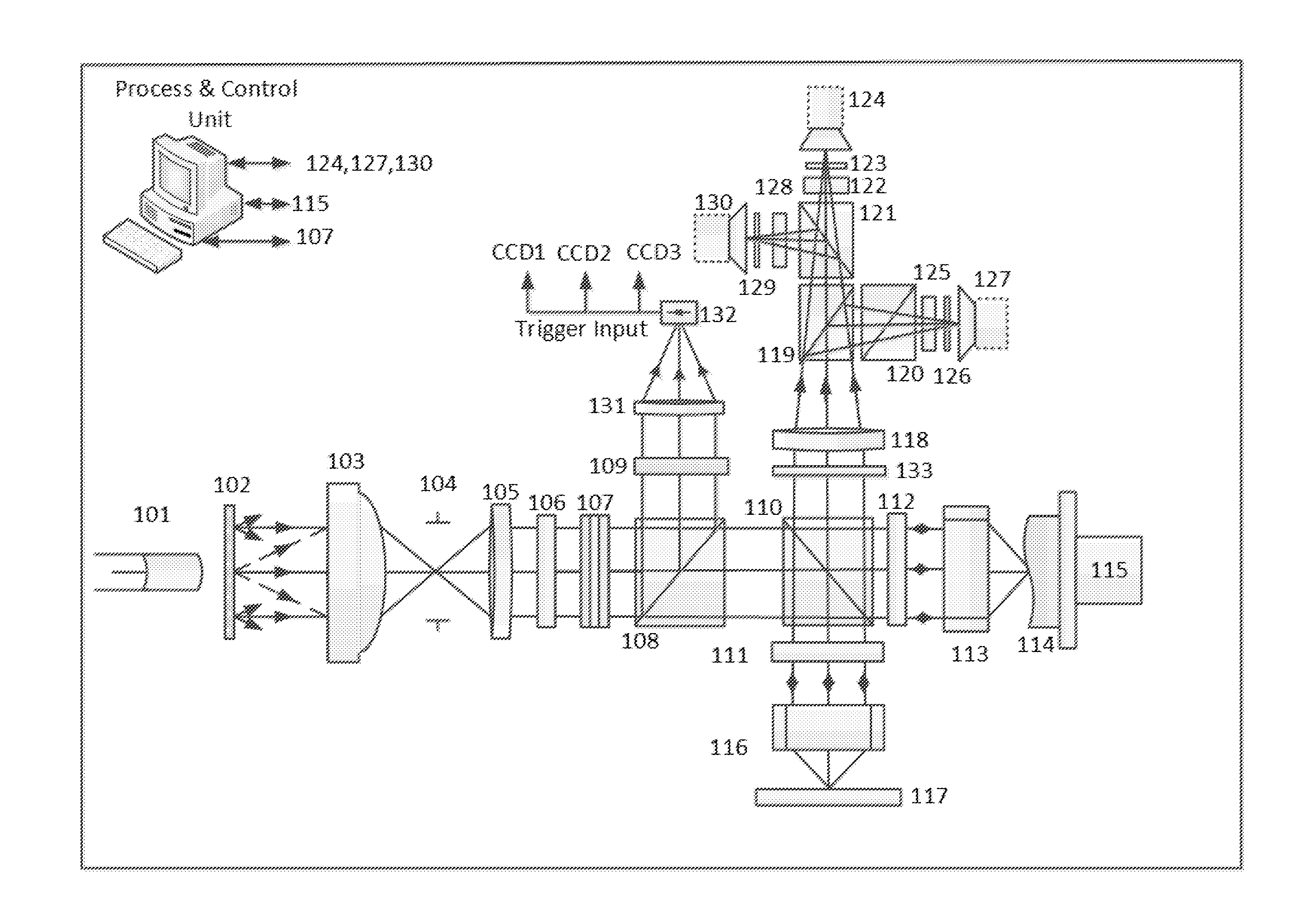
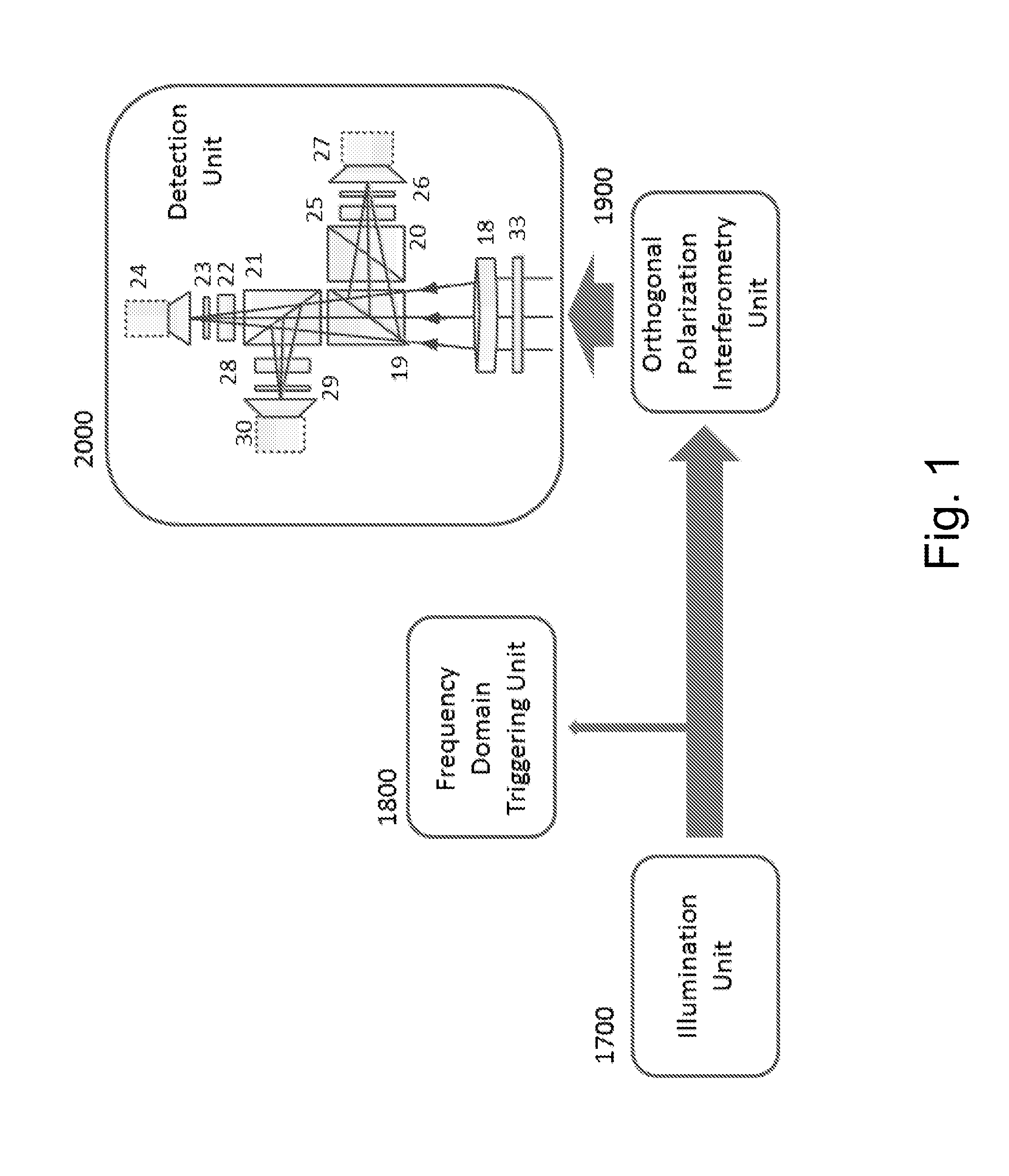
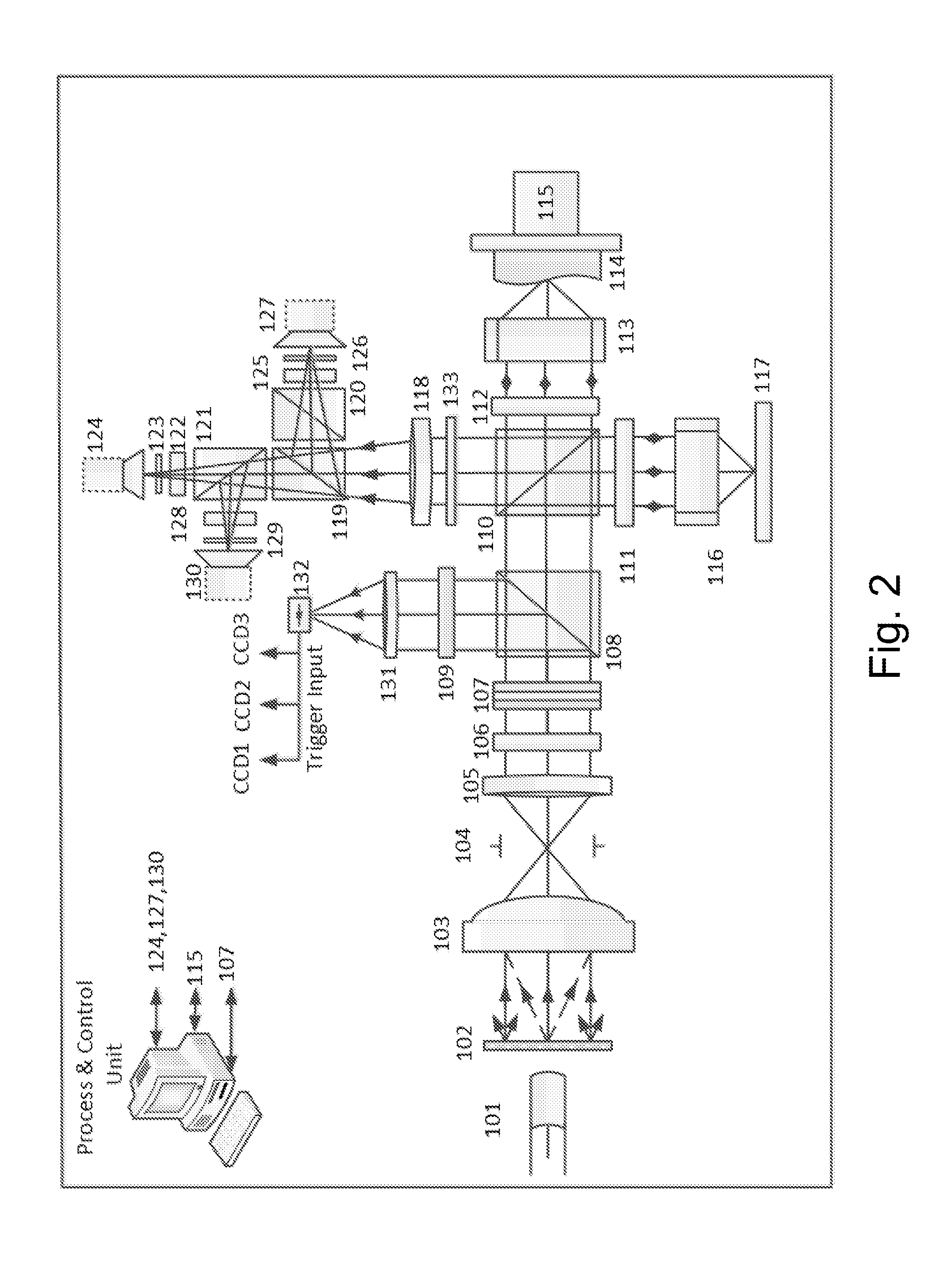
[0078]The invention is a system and method that enable obtaining ultra-high resolution interference, phase and OCT images at high speed. The system uses neither mechanical moving elements nor any optical / electro optical modulating means for obtaining the OCT images. Two OCT operating modes are available: for ultra-high resolution the system allows either spatial coherence TD-FF-OCT or temporal coherence TD-FF-OCT imaging, whereas for high resolution and ultra-high speed the system allows FD-FF-OCT imaging with full range imaging. In the TD mode, the OCT enface images are obtained in real time. In the FD mode, the 2D complex signal is reconstructed in real time. In both cases the method has the advantage of very high speed imaging with great immunity to noise.

[0079]By using three (alternatively two) parallel detectors, each equipped with an achromatic phase shifter, three phase shifted (alternatively two) interference images are grabbed simultaneously and in parallel (the entire fiel...


PUM


Abstract

The invention is a system and method that enable obtaining ultra-high resolution interference, phase and OCT images at high speed. The system uses neither mechanical moving elements nor any optical / electro optical modulating means for obtaining the OCT images. Two OCT operating modes are available: for ultra-high resolution the system allows either spatial coherence TD-FF-OCT or temporal coherence TD-FF-OCT imaging, whereas for high resolution and ultra-high speed the system allows FD-FF-OCT imaging with full range imaging. In the TD mode, the OCT enface images are obtained in real time. In the FD mode, the 2D complex signal is reconstructed in real time. In both cases the method has the advantage of very high speed imaging with great immunity to noise.

Description

FIELD OF THE INVENTION[0001]The invention is from the field of optical imaging. In particular the invention is from the field of real time high resolution three dimensional imaging.BACKGROUND OF THE INVENTION[0002]Publications and other reference materials referred to herein are numerically referenced in the following text and respectively grouped in the appended Bibliography which immediately precedes the claims.[0003]Optical coherence tomography (OCT) is a 3D imaging method that is mainly associated with the production of high resolution 3D images of multilayer semi transparent samples. This method was first demonstrated in the context of ophthalmology [1]. OCT development and application to the biomedical and biological optical imaging fields is rising every day. OCT relies on the light temporal coherence, interference and matter reflectivity (refraction index discontinuity) which are used to measure micro morphology of objects in a turbid environment [2]. Most OCT systems can be...

Claims


Application Information

Patent Timeline
Patent Type & Authority Applications(United States)
IPC IPC(8): G01B9/02G02B21/00G02B21/26G02B21/22
CPCG01B9/02081G02B21/22G02B21/0092G01B2290/70G02B21/26G01B9/02091G02B21/0056G02B27/10
Inventor SAFRANI, AVNERABDULHALIM, IBRAHIM
Owner B G NEGEV TECH & APPL LTD
Learn More