
Multi ultrasonic probe for scanning welded zone of tube

a multi-sonic, tube technology, applied in response signal detection, instruments, measurement devices, etc., can solve the problems of stress corrosion cracking (scc) at the welded portion, difficulty in accurately scanning the defects which exist in the inside of the welded zone and the depth of the defects, etc., to improve accuracy and reliability in results, reduce the time taken to perform, and detect accurately

Inactive Publication Date: 2017-03-02
ENESG
View PDF8 Cites 12 Cited by
  • Summary
  • Abstract
  • Description
  • Claims
  • Application Information

AI Technical Summary

Benefits of technology

The present invention proposes a multi ultrasonic probe for scanning the welded zone of a tube to accurately detect positions, shapes, and depths of defects through one scanning to significantly reduce the time required for ultrasonic scanning and improve accuracy and reliability of results obtained through ultrasonic scanning.

Problems solved by technology

Thus, when the electric heater sleeve or the nozzles for installing the RIDs are installed in the pressurizer or the hot leg / cold leg, which is mode of the foregoing material, by the welding, it is reported that stress corrosion cracking (SCC) occur at the welded portion.
Also, if the cracking advances, a loss of coolant accident (LOCA) may occur.
However, it is difficult to accurately scan the defects which exist in the inside of the welded zone and the depths of the defects.

Method used


Image

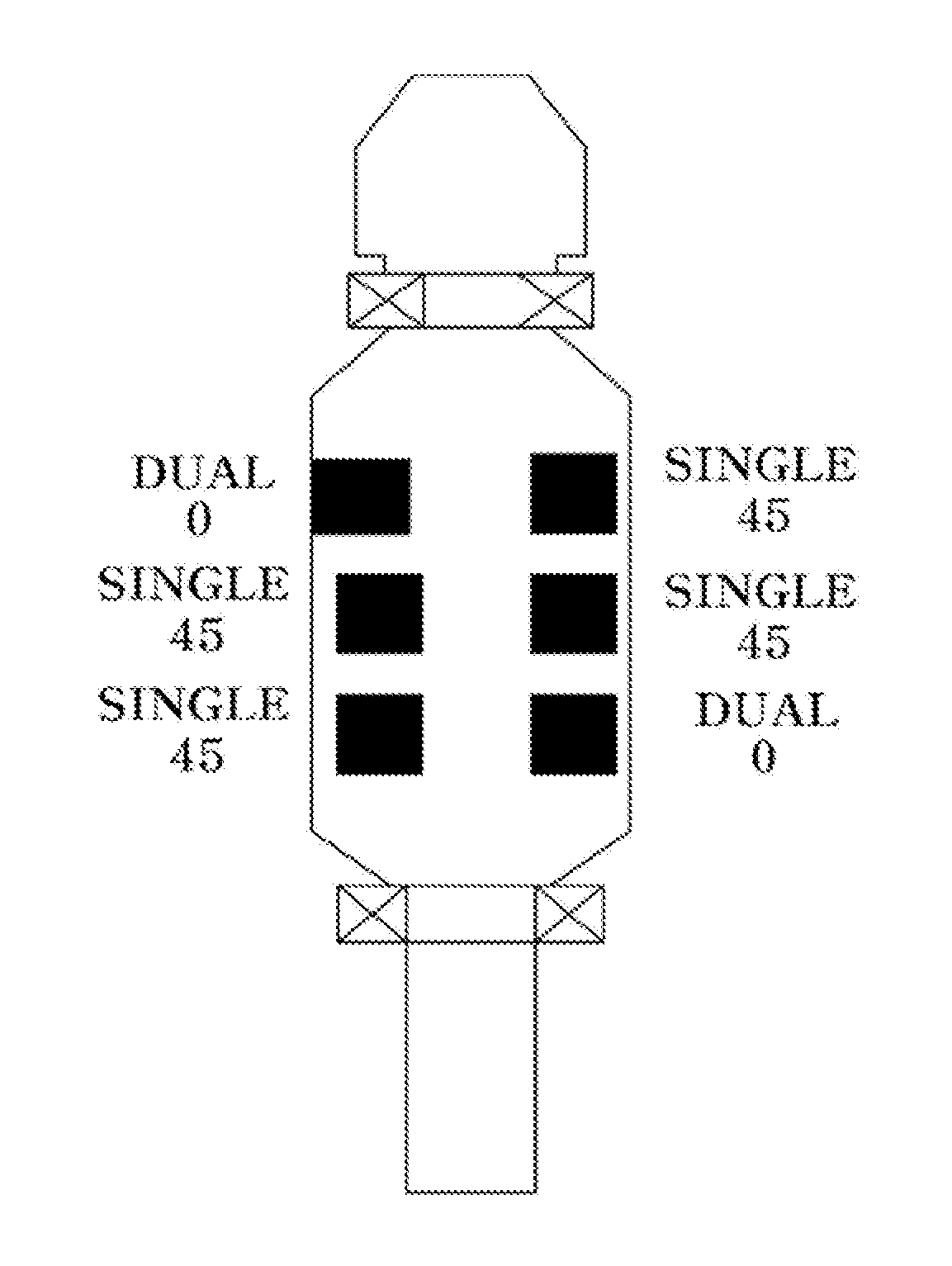
  • Multi ultrasonic probe for  scanning welded zone of tube
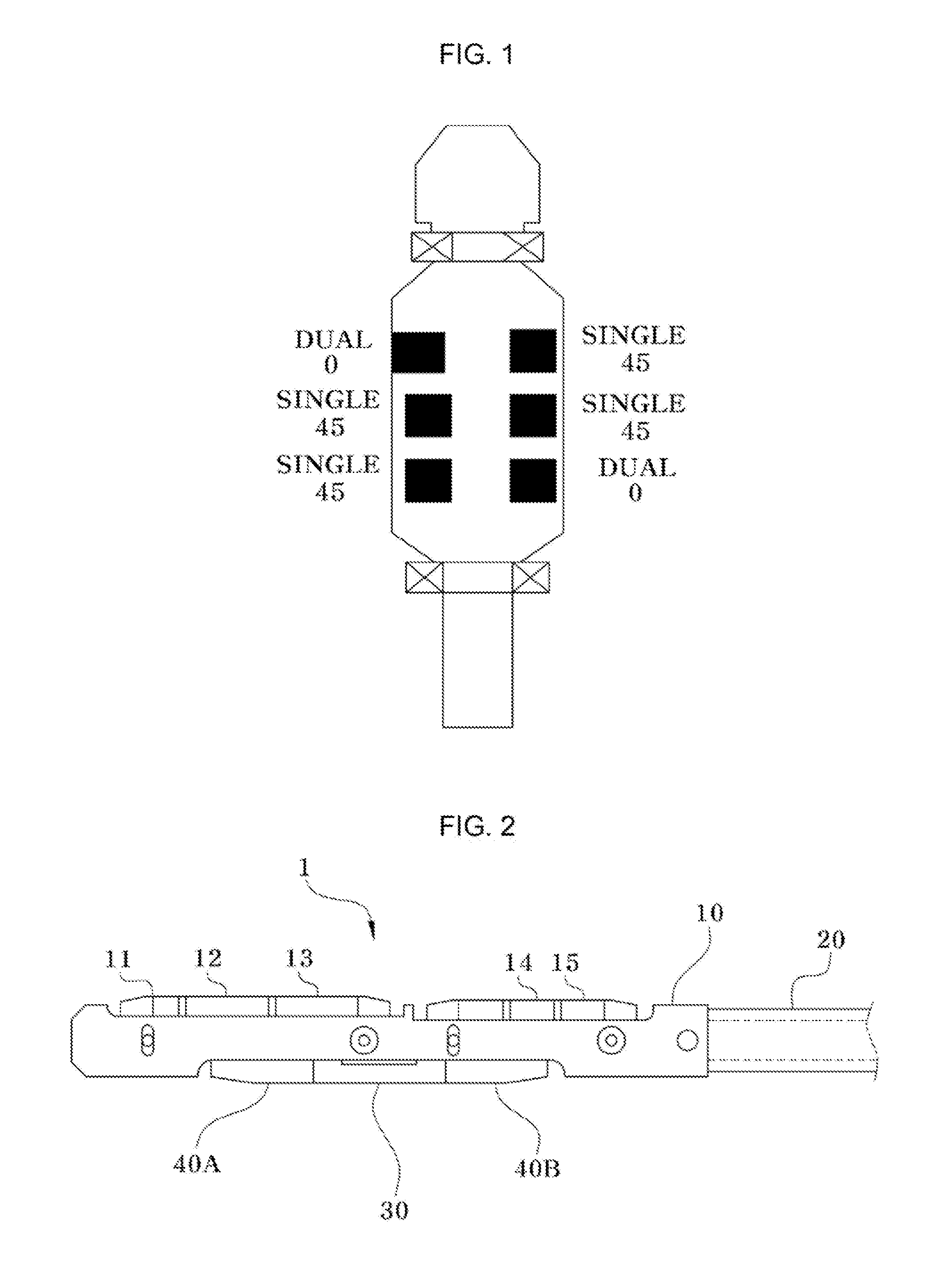
  • Multi ultrasonic probe for  scanning welded zone of tube
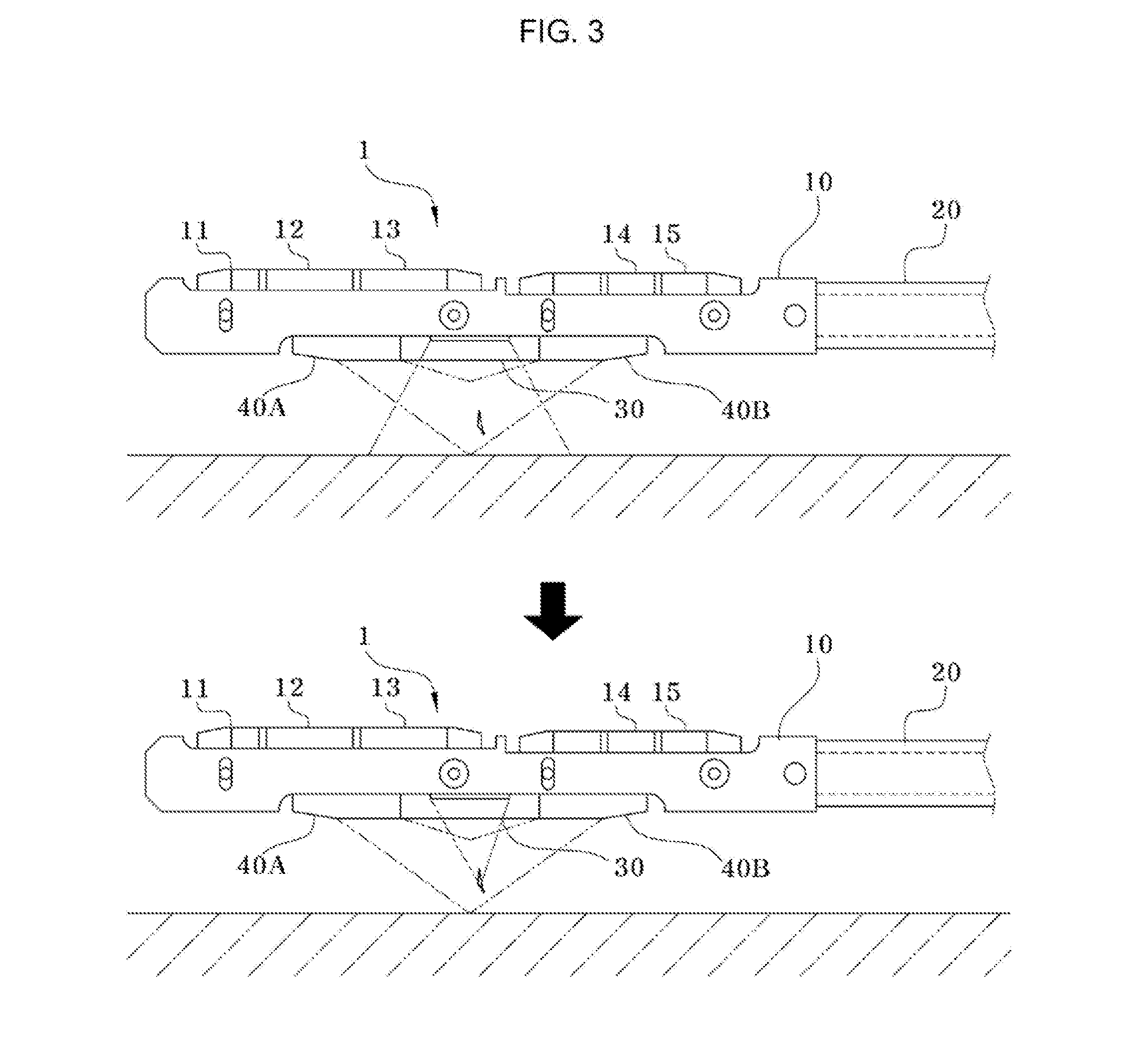
  • Multi ultrasonic probe for  scanning welded zone of tube

Examples


embodiment 1 (

(1) Embodiment 1 (Mode 1)

[0032]Embodiment 1 relates to a process in which a phased array ultrasonic sensor 30 and a pair of TOFD sensors 40A and 40B are individually used to perform scanning. In the mode 1, a probe body 10 is connected first to the outside of a welded zone of a target nozzle (a target tube), and then power is applied to the phased array ultrasonic sensor 30 to scan positions and shapes of defects. Thereafter, the phased array ultrasonic sensor 40 is turned off, and then power is applied to each of the pair of TOFD sensors 40A and 40B to scan depths of the defects. When the scanning is performed by individually using the phased array sensor 30 and the pair of TOFD sensors 40A and 40B, the analysis of each of the ultrasonic signals may have a difficulty due to mixing of the ultrasonic signals. However, since the signals received to the TOED sensors 40A and 40B are relatively weak, it is difficult to receive a signal generated by a fine defect.

embodiment 2 (

(2) Embodiment 2 (Mode 2)

[0033]Embodiment 2 relates to a process in which a phased array ultrasonic sensor 30 and a pair of TOFD sensors 40A and 40B are used together with each other to perform scanning. Embodiment 2 is same as Embodiment 1 except that power is applied to all of the phased array ultrasonic sensor 30 and the pair of TOFD sensors 40A and 40B to perform the scanning. As described above, when the scanning is performed by simultaneously using the phased array sensor 30 and the pair of TOFD sensors 40A and 40B, a signal emitted from the phases array ultrasonic sensor 30 may be focused to convert the signal having high energy into a diffracted signal. Thus, the ‘weak signal’ of the phased array ultrasonic sensor 30 may be compensated to easily scan fine defects. Thus, Embodiment 2 may be mainly used for intensively scanning a portion in which an occurrence of defects is predicted.

[0034]As described above, according to the present invention, the phased array ultrasonic sens...


PUM

PropertyMeasurementUnit
angleaaaaaaaaaa
angleaaaaaaaaaa
angleaaaaaaaaaa

Abstract

Provided is to ultrasonic probe used in scanning defect of welded zone of tube, the ultrasonic probe includes a probe body having a predetermined length, a connection bar connected to one end of the probe body, a phased array ultrasonic sensor installed on one side surface of the probe body to scan positions and shapes of the defects, and a pair of time of flight diffraction (TOFD) sensors respectively installed in the same line with the phased array ultrasonic sensor therebetween to scan depths of the defects. The present invention having the above-described configurations may significantly reduce a time taken to scan and accurately scan the positions, the shapes, and the depths of the defects.

Description

CROSS-REFERENCE TO RELATED APPLICATION[0001]This application claims priority to Korean Patent Application No. 10-2015-0119873 filed on Aug. 25, 2015 and all the benefits accruing therefrom under 35 U.S.C. 119, the contents of which are incorporated b reference in their entirety.BACKGROUND OF THE INVENTION[0002]The present invention relates a multi ultrasonic probe for scanning a welded zone of a tube, and more particularly to, a multi ultrasonic probe for scanning a welded zone of a tube, which is capable of accurately detecting positions and depths of defects such as cracking or corrosion in the welded zone of a small-diameter tube such as an electric heater sleeve of a pressurizer, a nozzle for drain / measurement of a steam generator, or a nozzle for installing as resistance temperature detector (RTD) of a hot leg / cold leg of a reactor coolant system (RCS) in a pressurized water reactor type nuclear power plant.[0003]A pressurized water reactor type nuclear power plants absorb ene...

Claims


Application Information

Patent Timeline
Patent Type & Authority Applications(United States)
IPC IPC(8): G01N29/04G01N29/36G01N29/265
CPCG01N29/041G01N29/265G01N2291/106G01N2291/267G01N29/36G01N29/069G01N29/225G01N29/262G01N2291/0258G01N2291/044G01N2291/102G01N2291/2634G01N2291/2636
Inventor SEONG, UN HAKRYU, SUNG WOOKIM, WON ILBAE, SU JINCHO, BYEONG LAEWON, JONG BUM
Owner ENESG
Learn More