
Device for powering an electrical appliance

a technology for electrical appliances and devices, applied in the field of electrical appliances, can solve the problems of real problems, complex solutions, and the cost of the power thus offered to users for free, and achieve the effect of avoiding electrical devices from being connected

Active Publication Date: 2017-03-02
ORANGE SA (FR)
View PDF27 Cites 1 Cited by
  • Summary
  • Abstract
  • Description
  • Claims
  • Application Information

AI Technical Summary

Benefits of technology

The invention is a power supply service that allows users to connect their electrical devices to a unit for a limited period of time without needing to activate the unit. If there is no movement in the first few seconds, the unit will cut off power to prevent fraud. Users can be easily billed based on the time they use the service. The unit can also be blocked after a few seconds to further prevent fraud, and users with SMS-capable devices can easily activate the service by sending an SMS. This simplifies the activation process and reduces costs.

Problems solved by technology

In the first case, this is a real problem for users who need to charge electrical devices such as their smartphones, tablets or laptop computers.
In the other case, the problem of the cost of the power thus offered to users for free arises, without forgetting the cost of maintaining the electrical sockets.
This issue arises, for example, in the case of charging electric vehicles, and solutions proposing charging points available to the general public exist.
The described solution is complex, however, and depends on standardized communication between the charging point and the vehicle via e.g. a CAN (Controller Area Network, ISO 11898) bus on board the vehicle.
This system has the drawback of depending on the addition of a payment terminal, thereby substantially increasing the cost of such an installation, not to mention the costs involved in maintaining such payment terminals.
This solution may however not be applied to existing electrical device pools without obliging each user to use a specific charging cable, e.g. integrating an NFC-type chip in order to identify the electrical device or its user.
This is a major drawback of these solutions.

Method used


Image

  • Device for powering an electrical appliance
  • Device for powering an electrical appliance
  • Device for powering an electrical appliance

Examples


Embodiment Construction

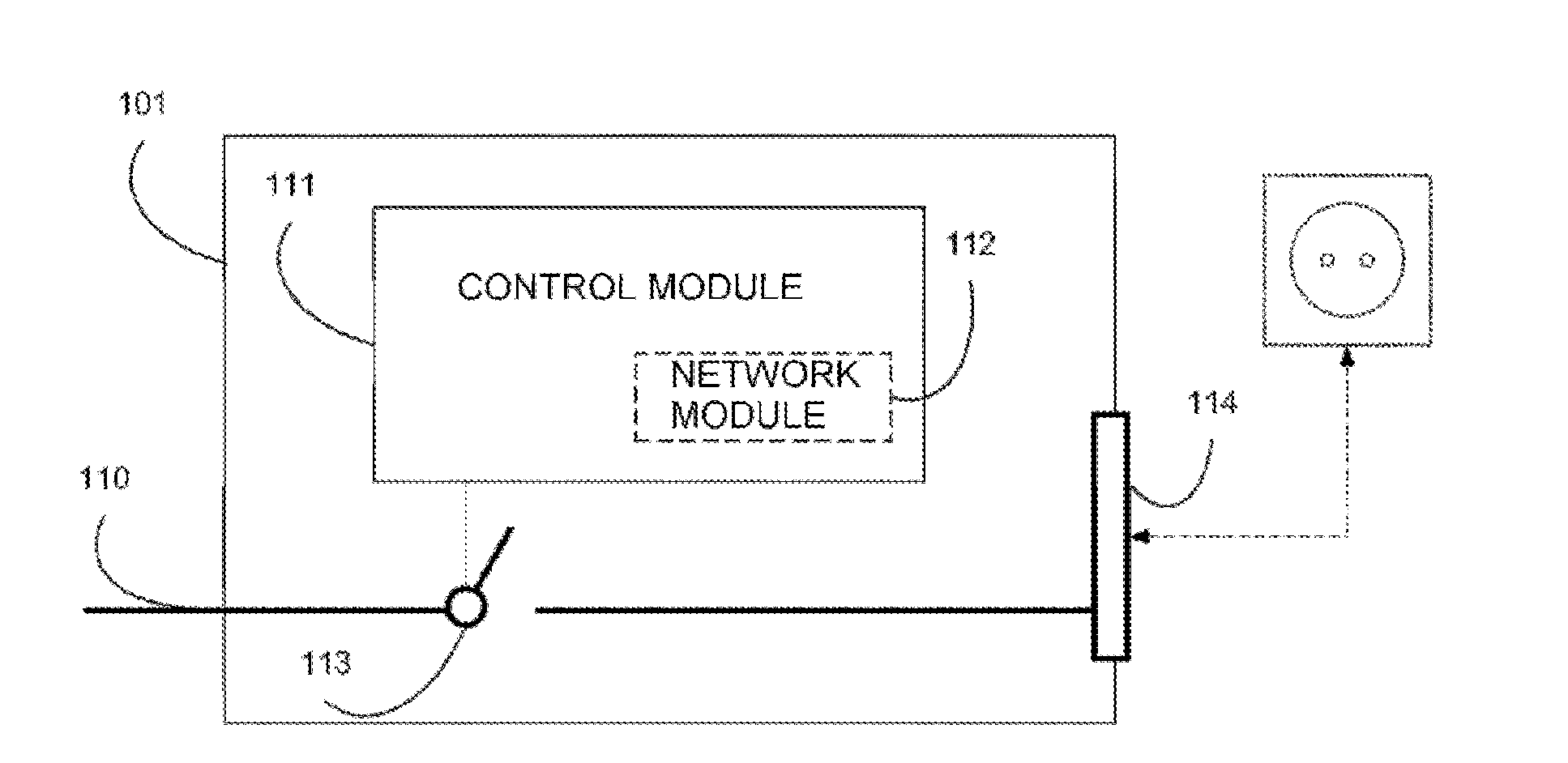
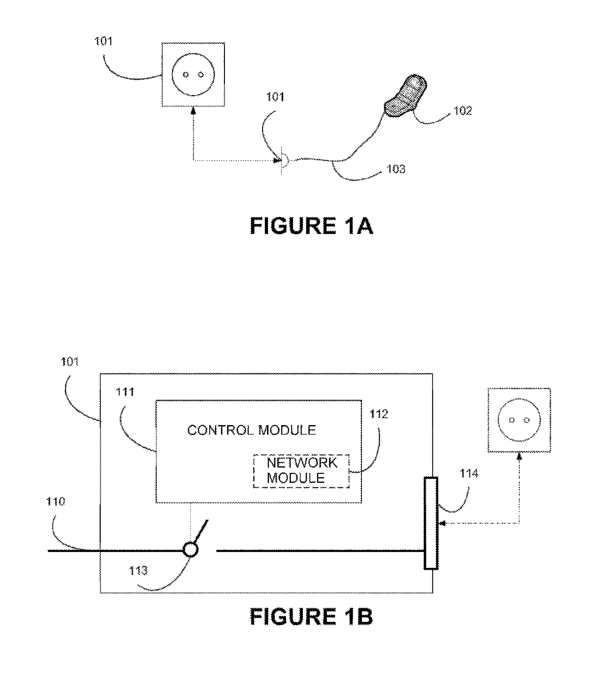
[0039]FIG. 1A shows an electrical power supply unit such as a female electrical socket conventionally used for allowing an electrical device to be connected via a cable equipped with a male plug. The electrical device is connected then to the electrical power supply unit by plugging in. This same electrical socket is connected to a power source, typically the domestic electrical network (not shown).

[0040]Depending on the implementations of the present invention, the power source used may be different. Specifically, it is possible to envisage the power source being a bank of batteries, potentially equipped with a voltage converter. It is also possible to envisage this same bank of batteries being charged by another power source, such as one or more wind turbines, solar panels, or any other power source potentially known to those skilled in the art.

[0041]In the rest of the present description, it will be assumed that the power source in question is an AC power source at 220 V, thereby...


PUM


Abstract

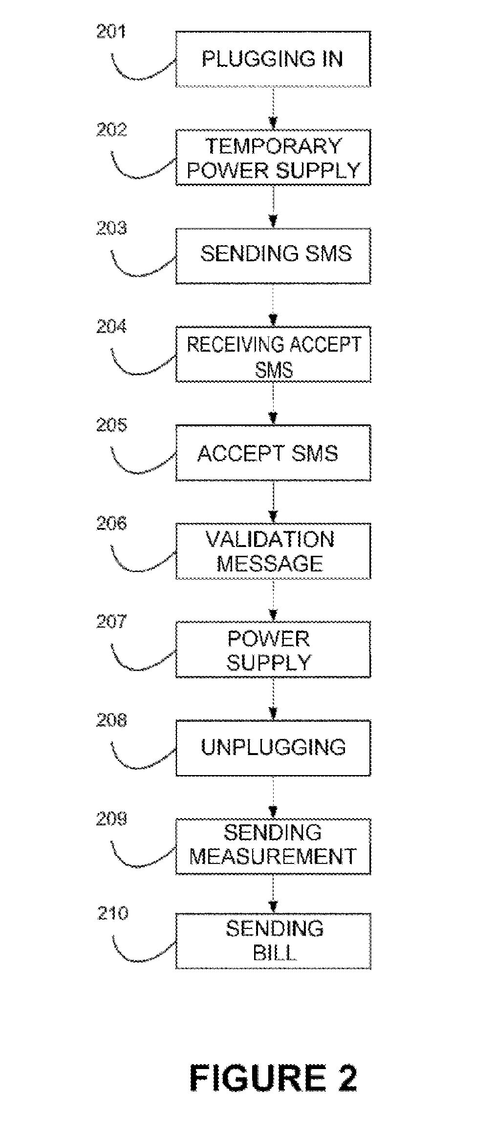
The present invention relates to a device allowing the electrical powering of an electrical appliance, having a remote control module allowing the activation of the electrical supply of the electrical appliance and allowing the reception of messages, the device including means for detecting the connection of the electrical appliance, the detection of the connection triggering a phase of electrical powering of the electrical appliance for a first duration, and, on receipt of a message during the first duration, maintaining the electrical supply of the electrical appliance beyond the first duration.

Description

CROSS-REFERENCE TO RELATED APPLICATIONS[0001]This application is a Section 371 National Stage application of International Application No. PCT / FR2015 / 050362, filed Feb. 13, 2015, the content of which is incorporated herein by reference in its entirety, and published as WO 2015 / 124854 on Aug. 27, 2015, not in English.TECHNICAL FIELD OF THE INVENTION[0002]The present invention relates generally to the field of units for supplying power to electrical devices and, more specifically, that of power supply units allowing electrical devices to be supplied with power while allowing this power supply to be billed.TECHNOLOGICAL BACKGROUND[0003]Access to electrical sockets for charging the battery of, or supplying electrical power to, an electrical device is currently often either non-existent or free in public places such as hotels, stations, trains, airports, etc.[0004]In the first case, this is a real problem for users who need to charge electrical devices such as their smartphones, tablets ...

Claims


Application Information

Patent Timeline
Patent Type & Authority Applications(United States)
IPC IPC(8): G06Q50/06G06Q30/04H02J50/80
CPCG06Q50/06G06Q30/04H02J50/80H02J7/0047G06Q20/145G07F15/006H02J7/00
Inventor PUHARRE, MICHELCHERBOURG, FABIEN
Owner ORANGE SA (FR)
Learn More