Electronic power module with enhanced thermal dissipation and manufacturing method thereof

a technology of electronic power modules and thermal dissipation, which is applied in the direction of printed circuit board receptacles, conductive pattern formation, and semiconductor/solid-state device details, etc., can solve the problems of excessive thickness and reduce production efficiency, and achieve the effect of improving thermal dissipation

Active Publication Date: 2017-03-02
STMICROELECTRONICS SRL
View PDF30 Cites 36 Cited by
  • Summary
  • Abstract
  • Description
  • Claims
  • Application Information

AI Technical Summary

Benefits of technology

[0010]Some embodiments of the disclosure are an electronic power module equipped with a packaging structure with enhanced thermal dissipation, and a method for manufacturing the electronic power module that overcomes disadvantages of known solutions.

Problems solved by technology

However, the use of the solder balls for mutual coupling between the substrates and for coupling between the dice and the substrates is the cause of an excessive thickness of the resulting stack, as well as of introduction of parasitic effects that are generated on account of the presence of the melting regions between the balls and the substrates.
Furthermore, embodiments of a known type entail long process steps in terms of manufacturing time, causing a reduction of the production efficiency.

Method used


Image

  • Electronic power module with enhanced thermal dissipation and manufacturing method thereof
  • Electronic power module with enhanced thermal dissipation and manufacturing method thereof
  • Electronic power module with enhanced thermal dissipation and manufacturing method thereof

Examples


Embodiment Construction

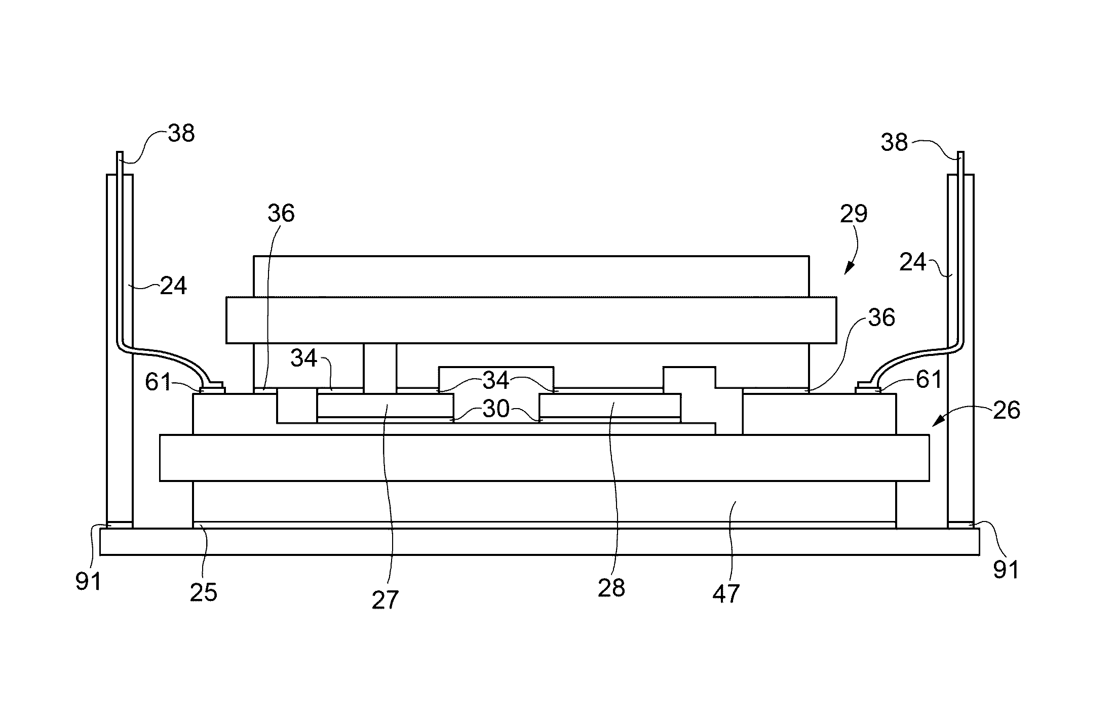
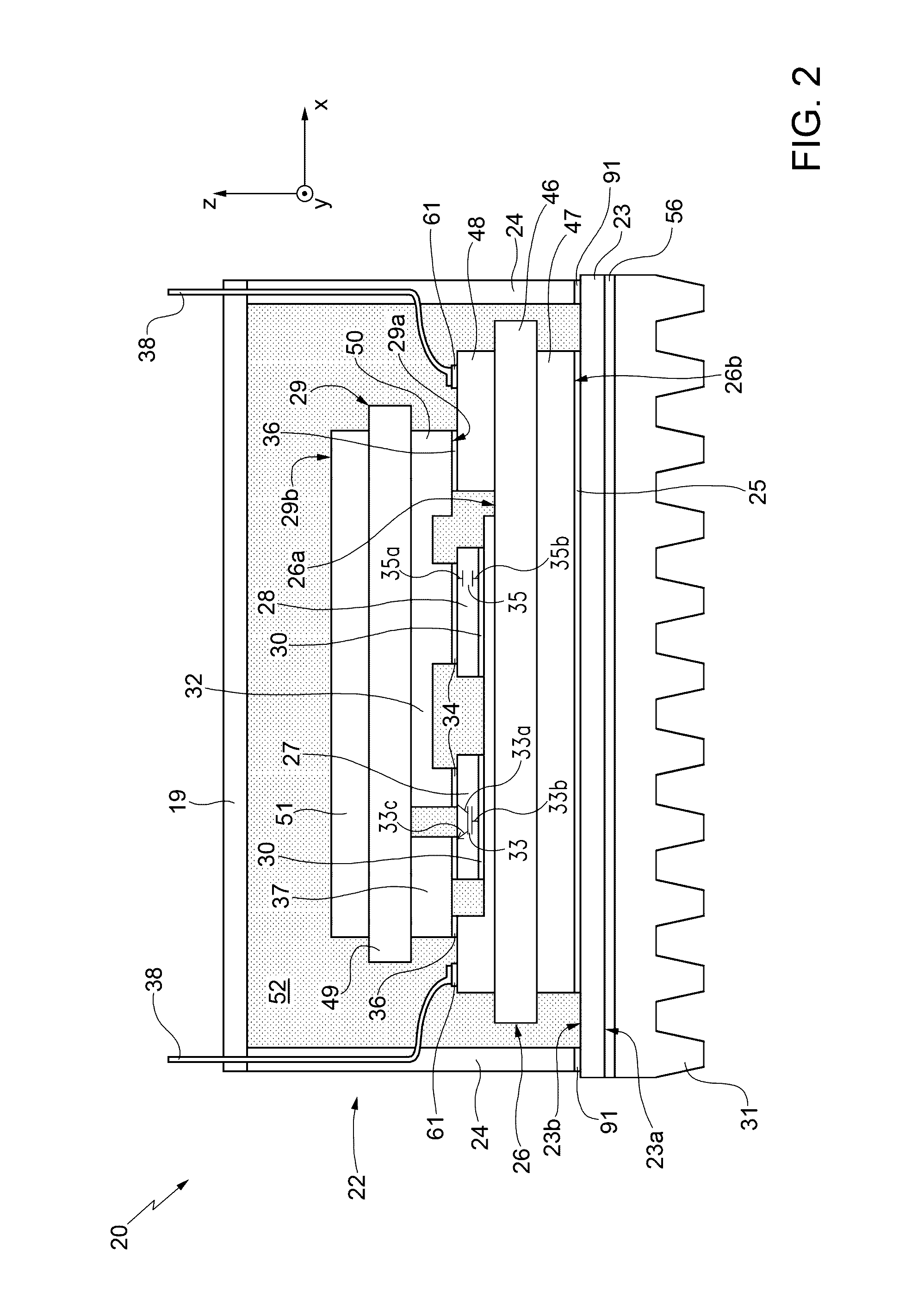
[0025]FIG. 2 shows, in lateral cross-sectional views and in a triaxial system of axes X, Y, Z, a power module (or electronic power device) 20 according to one aspect of the present disclosure.

[0026]The power module 20 comprises:[0027]a package 22, including a base plate 23 lying in the plane XY, of electrically and thermally conductive material, for example metal material such as copper, and side walls 24, which extend parallel to the planes XZ and YZ along perimetral portions of the base plate 23; the side walls 24 are of insulating material, for example plastic material;[0028]a bottom substrate 26 obtained with DBC technology thermally coupled to a second face 23b, opposite to the first face 23a, of the base plate 23 by a first coupling region 25 including a sintered paste of electrically and thermally conductive material, in particular a paste including silver;[0029]a first die 27 and a second die 28, which are mechanically and thermally coupled to a face 26a of the bottom substr...


PUM


Abstract

An electronic power module comprising a case that houses a stack, which includes: a first substrate of a DBC type or the like; a die, integrating an electronic component having one or more electrical-conduction terminals, mechanically and thermally coupled to the first substrate; and a second substrate, of a DBC type or the like, which extends over the first substrate and over the die and presents a conductive path facing the die. The die is mechanically and thermally coupled to the first substrate by a first coupling region of a sintered thermoconductive paste, and the one or more conduction terminals of the electronic component are mechanically, electrically, and thermally coupled to the conductive path of the second substrate by a second coupling region of sintered thermoconductive paste.

Description

BACKGROUND[0001]Technical Field[0002]The present disclosure relates to an electronic power module provided with a packaging structure with enhanced thermal dissipation and to a method for manufacturing the electronic power module.[0003]Description of the Related Art[0004]As is known, in the manufacture of semiconductor devices, packaging is the final step that transforms a processed substrate, including electronic or electromechanical functional elements, into a component that may be mounted on a printed circuit board (PCB). The package provides a protection for the substrate and provides the electrical connections through which it is possible to supply signals to the functional elements and acquire signals coming therefrom.[0005]To provide for an ever-increasing integration and reduction in size, the packaging methods currently used include wafer-level packaging (WLP) and 3D packaging. Further solutions envisage surface-mount devices (SMDs), which enable a further reduction of the ...

Claims


Application Information

Patent Timeline
Patent Type & Authority Applications(United States)
IPC IPC(8): H05K1/02H05K13/00H05K3/10H05K1/11H01L23/00H01L25/18H01L23/367H01L23/492H01L23/34H01L25/00H01L23/08H01L23/053H01L23/373H01L23/31H01L23/29H05K7/14
CPCH05K1/0203H01L2924/19107H05K13/0023H05K3/10H05K1/115H01L24/33H01L25/18H01L23/3675H01L23/492H01L23/34H01L24/83H01L25/50H01L24/27H01L23/08H01L23/053H01L23/3735H01L23/3114H01L23/296H05K2201/06H01L2224/29139H01L2224/32227H01L2924/15153H01L2924/13055H01L2924/1203H01L2224/8384H01L2224/83192H01L2224/33181H05K7/1427H01L23/24H01L23/36H01L23/3737H01L23/49811H01L23/49833H01L23/49838H01L23/5385H01L2224/40225H01L2224/371H01L2224/37147H05K13/00H01L25/071H01L25/072
Inventor RIZZA, ROBERTOMINOTTI, AGATINOMONTALTO, GAETANOSALAMONE, FRANCESCO
Owner STMICROELECTRONICS SRL
Why Eureka
Try Eureka