
System and method for identifying a condition of rotary machine components

Active Publication Date: 2017-03-09
GENERAL ELECTRIC CO
View PDF6 Cites 8 Cited by
  • Summary
  • Abstract
  • Description
  • Claims
  • Application Information

AI Technical Summary

Benefits of technology

The patent describes an imaging and analysis system for a rotary machine component. The system uses an image capture device to capture image data from electromagnetic radiation reflected or transmitted through the component. An image processor then processes the data, and a control system automatically identifies any condition of the component by comparing the processed data to stored reference data. The technical effect of this system is to provide a non-destructive method for inspecting components of rotary machines for defects and damage, improving efficiency and reliability.

Problems solved by technology

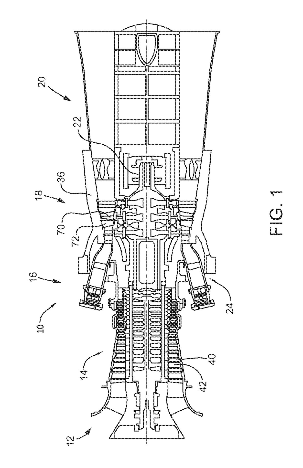
Rotary machines typically include components, such as but not limited to rotor blades, that are subject to wear and / or damage during operation of the rotary machine.
However, an ability of at least some such systems to consistently identify and classify damage is limited by variations in parameters of the captured images, such as but not limited to variations in position and orientation of the component relative to the imaging device and variations in lighting / illumination conditions.
In addition, an ability of at least some such systems to consistently identify and classify damage is limited by a subjectivity of a human analyst of the images.

Method used


Image

  • System and method for identifying a condition of rotary machine components
  • System and method for identifying a condition of rotary machine components
  • System and method for identifying a condition of rotary machine components

Examples


Embodiment Construction

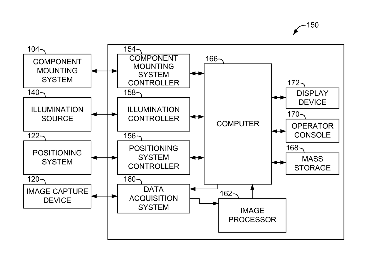
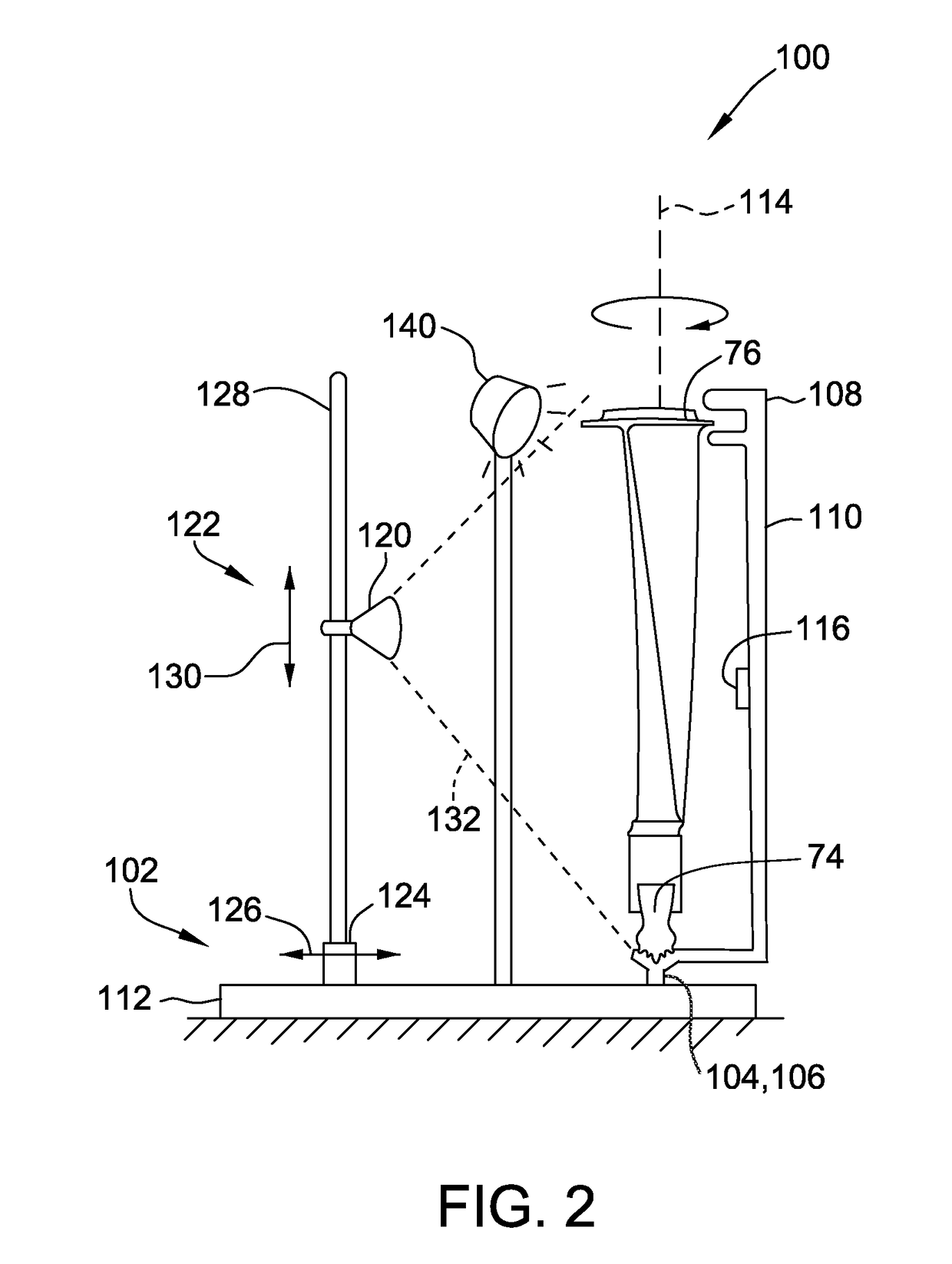
[0010]The exemplary components and methods described herein overcome at least some of the disadvantages associated with known systems for identifying wear and / or damage to components of rotary machines. The embodiments described herein provide a computer configured to perform a direct comparison of processed data obtained from images of a component under evaluation with stored reference data to automatically identify the condition of a component. The embodiments described herein also provide a use of reference data associated with an ideal or condition-specific component of the type under evaluation. Certain embodiments also provide a mounting rig configured to selectively present a received component of the rotary machine in at least one preselected position and orientation relative to an image capture device.

[0011]Unless otherwise indicated, approximating language, such as “generally,”“substantially,” and “about,” as used herein indicates that the term so modified may apply to onl...


PUM


Abstract

An imaging and analysis system for a component of a rotary machine includes an image capture device operable to capture image data from at least one selected type of electromagnetic radiation that is at least one of reflected from and transmitted through the component. The system also includes an image processor configured to generate processed data from the captured image data. The system further includes a control system configured to automatically identify a condition of the component by comparing the processed data to stored reference data. The reference data is stored in a format that enables direct comparison to the processed data.

Description

CROSS REFERENCE TO RELATED APPLICATIONS[0001]Cross reference is hereby made to co-pending application Ser. No. TBD entitled “METHODS AND SYSTEMS FOR DETERMINING CAUSES OF CONDITIONS IN COMPONENTS OF ROTARY MACHINES,” filed on the same day and having the same inventors as the present application, the disclosure of which is hereby incorporated by reference in its entirety.BACKGROUND[0002]The field of the disclosure relates generally to rotary machines, and more particularly to identification of a condition, such as wear and / or damage, to components of rotary machines.[0003]Rotary machines typically include components, such as but not limited to rotor blades, that are subject to wear and / or damage during operation of the rotary machine. At least some known systems capture images of such components, such as visible spectrum, x-ray, or other types of images, to facilitate identification and classification of such wear and / or damage, for example by comparison to previously captured images...

Claims


Application Information

Patent Timeline
IPC IPC(8): G06T7/00F01D21/00H04N5/232F04D27/00H04N5/32H04N5/225F01D5/12F04D29/32
CPCG06T7/001F01D5/12F01D21/003F04D29/324F04D27/001G06T7/0008G06T2207/10116H04N5/2253H04N5/23296F05D2220/32G06T2207/30164G06T2207/10152H04N5/32F05D2260/80F05D2270/8041F05D2250/70H04N23/60H04N23/54H04N23/69
Inventor SEELY, MELISSA ANNSEELY, WILLIAM FORRESTER
Owner GENERAL ELECTRIC CO
Learn More