Magnet fixing structure for electric rotary machine

a technology of fixing structure and electric rotary machine, which is applied in the direction of dynamo-electric machines, magnetic circuit rotating parts, magnetic circuit shape/form/construction, etc., can solve the problems of difficult to maintain the bonding strength, easy degradation of adhesive agents in hot environments, and broken magnets rigidly held by adhesives, etc., to prevent broken, improve the quality of products, and easy degradation

Active Publication Date: 2010-03-30
MITSUBA CORP
View PDF15 Cites 47 Cited by
  • Summary
  • Abstract
  • Description
  • Claims
  • Application Information

AI Technical Summary

Benefits of technology

[0018]Therefore, the magnets are prevented from being broken when an adhesive agent is used because of the difference in the coefficient of linear expansion of each component. Additionally, since no adhesive agent is used, the above-identified problem in that the bonding strength can be dispersed according to the bonding conditions and the quantity of the applied adhesive and the adhesive agent can easily be degraded in a hot environment has nothing to do with a magnet fixing structure according to the present invention so that it is possible to improve the quality of the product. Furthermore, since the holder members are aligned by the holder anchoring grooves, it is possible to accurately align and rigidly anchor the magnets to stabilize the product characteristics. Still additionally, according to the present invention, only by means of an assembling operation of press-fitting the magnets, neither the adhesive agent applying operation nor the time for hardening the adhesive agent in the assembling process is required to consequently reduce the number of manufacturin

Problems solved by technology

However, the method of rigidly fitting a magnet to a rotor core or the like by means of adhesive is accompanied by the following problems.
Firstly, the coefficient of linear expansion of the rotor of such an electric rotary machine varies from component to component so that the magnet rigidly held by adhesive can become broken when it is heated to a high temperature level.
Secondly, when the magnet is rigidly held by means of adhesive, the bonding strength can be dispersed according to the bonding conditions and the quantity of the applied adhesive.
Additionally, the adhesive agent can easily be degraded in a hot environment.
Then, it is difficult to maintain the bonding strength to a desired level and hence the quality of the product may not be guaranteed.
Furthermore, it is difficult to accurately bon

Method used


Image

  • Magnet fixing structure for electric rotary machine
  • Magnet fixing structure for electric rotary machine
  • Magnet fixing structure for electric rotary machine

Examples


embodiment 1

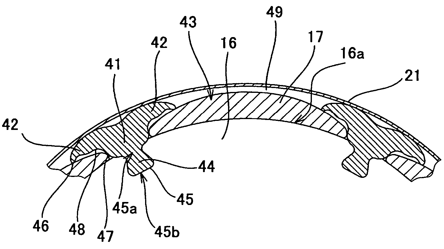
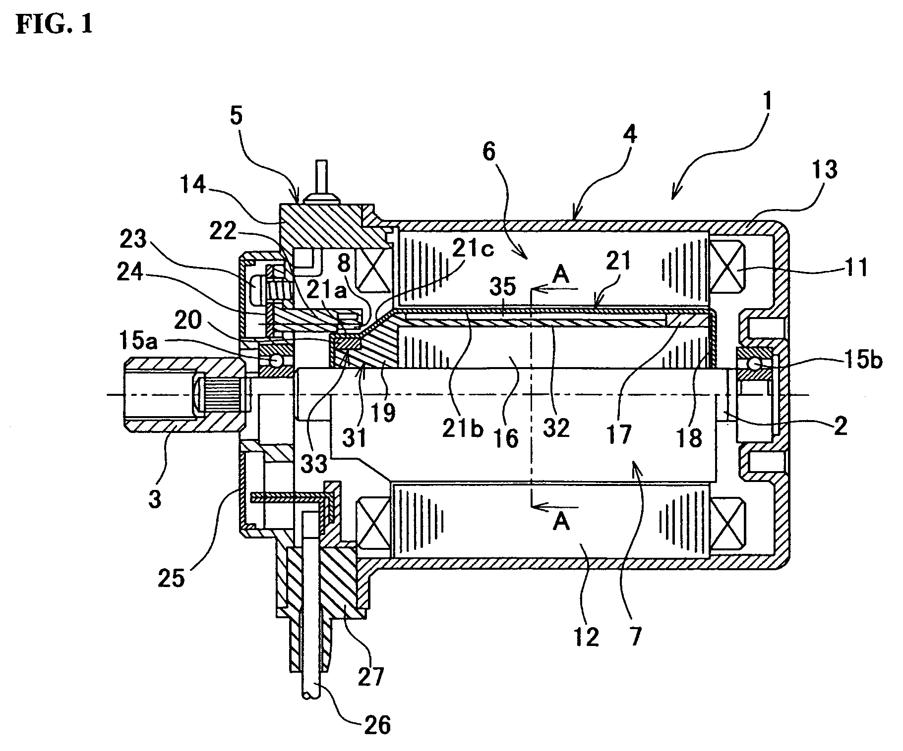
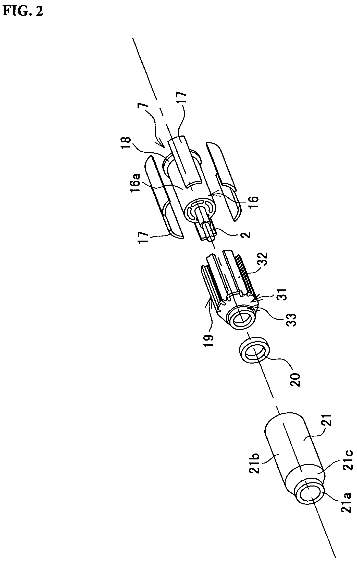
[0079]FIG. 1 is a schematic cross sectional view of a brushless motor realized by using Embodiment 1 of a magnet fixing structure according to the present invention. FIG. 2 is an exploded schematic perspective view of the brushless motor of FIG. 1. The brushless motor (to be referred to simply as motor hereinafter) of FIGS. 1 and 2 is to be used as drive source for an EPS. The motor 1 supplies steering assisting power according to the steering angle and the running speed of the vehicle as the driver operates a steering wheel. The rotor shaft (rotary shaft) 2 of the motor 1 is linked to the input shaft of a gear box (not shown) by way of joint 3. The revolutions of the motor 1 are reduced appropriately in the gear box and subsequently transmitted to the steering column of the vehicle so that the steering power of the vehicle is assisted by the rotary power of the motor 1.

[0080]Roughly speaking, the motor 1 comprises a motor section 4 and a sensor section 5. The motor section 4 includ...

embodiment 2

[0100]Embodiment 2 of the present invention differs from Embodiment 1 in that the projections and the grooves of the engagement arrangement of the magnet fixing structure are inverted. FIG. 7 is an enlarged schematic cross sectional view of the second embodiment of a magnet fixing structure according to the present invention. In the following embodiments, the components which are the same as or similar to those of the first embodiment are denoted respectively by the same reference symbols and will not be described further.

[0101]Holder anchoring projections 51 are formed on the outer periphery of the rotor core 16 for the holder anchoring sections of this embodiment. The holder anchoring projections 51 extend along the rotary shaft. A total of six holder anchoring projections 51 are arranged peripherally at regular intervals. The front end part 51a of each of the holder anchoring projections 51 is made broader than the base part 51b thereof. On the other hand, each holder arm 32 has ...

embodiment 3

[0104]Embodiment 3 differs from Embodiment 1 in that the rotor magnets 17 are radially skewed by using a magnet fixing structure similar to that of the first embodiment. FIG. 8 is a schematic cross sectional view of the brushless motor where the rotor magnets are skewed.

[0105]Of the rotor 53 of FIG. 8, the rotor magnets 17 indicated by hatching are skewed to step aside (be offset) in the radial direction between the front half and the rear half thereof. Note that a resolver is used for the rotor 53 as described in the last part of the description of Embodiment 1. Magnet holder 54 is used for the front rotor 53a whereas magnet holder 55 is used for the rear rotor 53b. The magnet holder 54 is realized by axially reducing the length of the holder arms 32 of the magnet holder 19 of Embodiment 1. On the other hand, the magnet holder 55 does not have any holder base 31 of the magnet holder 19. In other words, the magnet holder 55 has only holder arms 32.

[0106]The rotors 53a, 53b are forme...


PUM


Abstract

Holder anchoring grooves are arranged on the outer periphery of a rotor core so as to extend axially. A holder arm having a substantially T-shaped cross section is fitted to each of the holder anchoring grooves. The holder arm has a main body section, an engaging projection and magnet holding pieces. The engaging projection is engaged with the corresponding one of the holder anchoring grooves. Each of the magnet holding pieces includes a first contact section, a second contact section and a non-contact area. A magnet containing section is defined by the magnet holding pieces that are located vis-à-vis relative to each other of any two adjacently located holder arms and the outer peripheral surface of the rotor core. In the magnet containing sections, a rotor magnet is press fitted and anchored from the shaft direction. Thus, there is provided a magnet fixing structure that can accurately anchor magnets to a rotor core or the like at low cost.

Description

TECHNICAL FIELD[0001]This invention relates to a magnet fixing structure of an electric rotary machine such as a motor and an electric generator. More particularly, the present invention relates to a magnet fixing structure of an electric rotary machine that can rigidly hold a magnet without using any adhesive agent.BACKGROUND ART[0002]A permanent magnet field system is conventionally used in many small electric motors and electric generators. In this case, a magnet is often rigidly fitted to a stator or a rotor by means of adhesive. After bonding the magnet to the rotor or the stator, a magnet cover is mounted thereon in most cases. For example, many motors being used for electric power steering systems (to be referred to simply as EPS hereinafter) are provided with a magnet cover that is arranged around the rotor magnet in order to prevent the motor from falling into a locked condition when the magnet comes off or becomes broken.[0003]Known methods for rigidly holding a magnet arr...

Claims


Application Information

Patent Timeline
IPC IPC(8): H02K21/12H02K1/27
CPCH02K1/278
Inventor OCHIAI, TAKAYUKINEGISHI, SATORU
Owner MITSUBA CORP
Why Eureka
Try Eureka