
Cooling apparatus

a technology of cooling apparatus and cooling chamber, which is applied in the direction of mechanical equipment, machines/engines, underground tubes, etc., can solve the problems of affecting the output of wind farms, affecting the transmission of power, and only cooled insufficient proportions of power-cable arrangements exposed to air. , to achieve the effect of improving and cost-effective power-cable cooling

Active Publication Date: 2017-03-16
SIEMENS GAMESA RENEWABLE ENERGY AS
View PDF17 Cites 17 Cited by
  • Summary
  • Abstract
  • Description
  • Claims
  • Application Information

AI Technical Summary

Benefits of technology

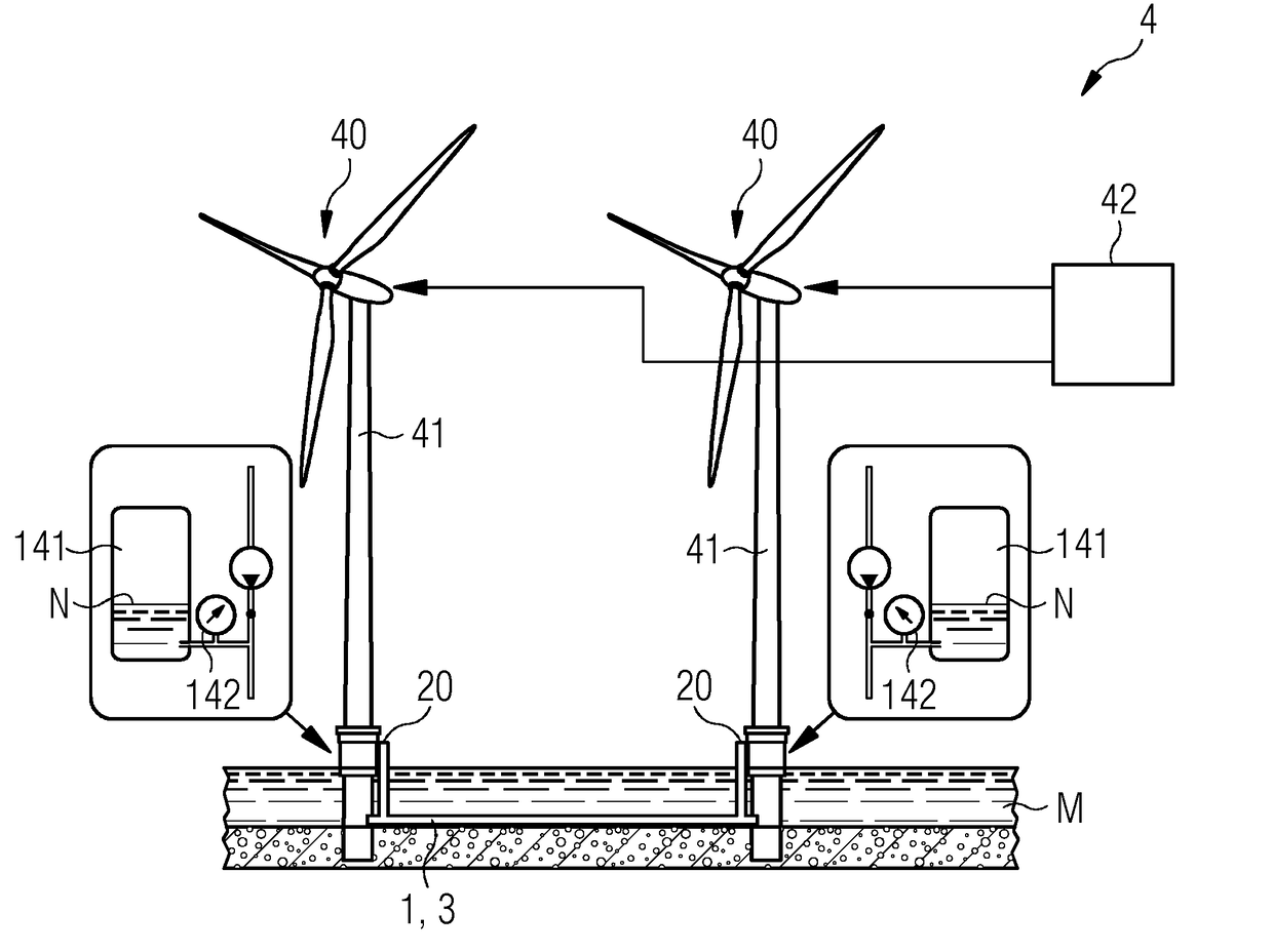
The cooling apparatus described in this patent has several technical benefits. Firstly, it allows for the effective cooling of a heated-up cable arrangement by using water, which has good heat conducting properties. Secondly, the apparatus retains a layer of water which helps to displace any air pockets and improve cooling performance. Additionally, the pressure of the water can be adjusted using a pressure regulator, providing valuable information on the sealing of the cooling system, temperature of the cable, etc.

Problems solved by technology

Accordingly, that portion of the power-cable arrangement which is exposed to the air is cooled only to an insufficient extent, in particular when the wind turbine is operating at full, or more or less full, power.
Nevertheless, it is possible for disadvantageous “hot spots” to arise in the energy conductors, and the transmission of power is impaired.
In order to avoid such “hot spots” in the power-cable arrangement of a wind turbine, it is necessary for the power of the latter to be restricted, and this, in turn, adversely affects the output of the wind farm.
In particular in the case of a wind farm having a multiplicity of wind turbines, such temperature monitoring can be very complex and expensive.
If the water temperature rises, this results in an increase in the pressure.
If the information indicates a pressure loss, the control device can conclude that there is a leak in the cooling-water apparatus.
For example, the outer pipe may be damaged by external influences.

Method used


Image

  • Cooling apparatus
  • Cooling apparatus
  • Cooling apparatus

Examples


Embodiment Construction

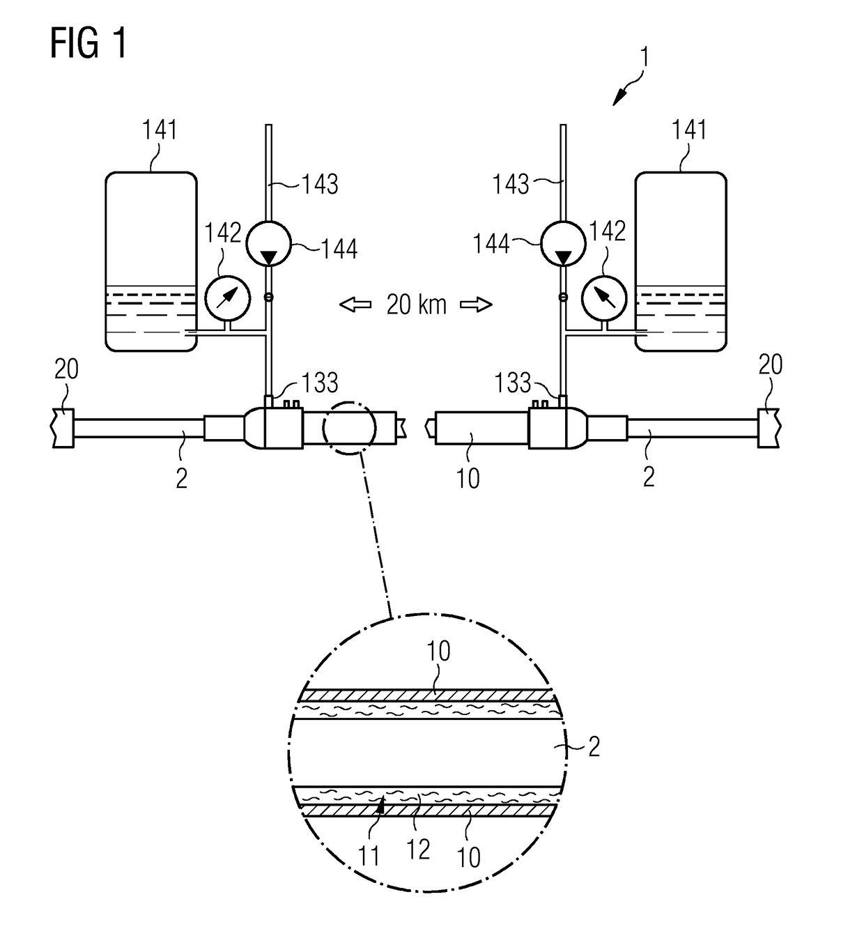
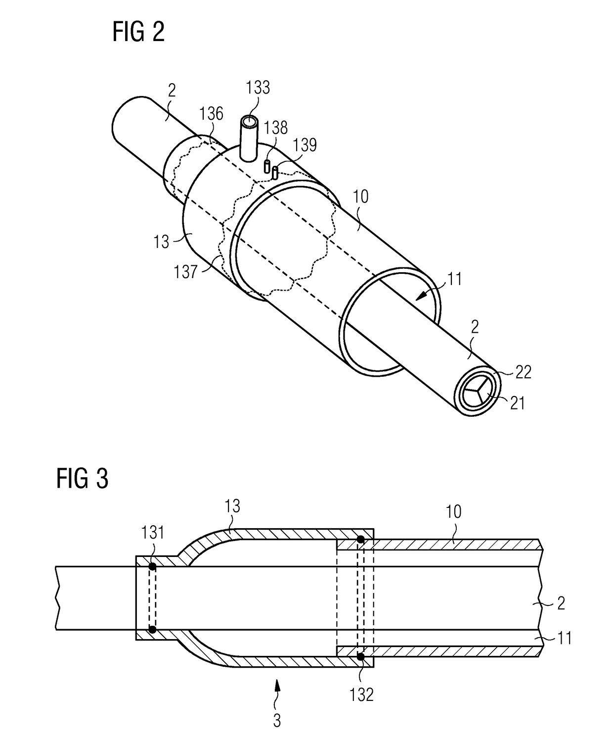
[0037]FIG. 1 shows an exemplary embodiment of a cooling apparatus 1 according to the invention which comprises an outer pipe 10, which is arranged around a cable arrangement 2. The cable arrangement 2 may be of any desired length and can extend over a number of kilometers between its two end points 20. The cable arrangement 2 serves, in particular, as an energy source and routes a number of energy conductors for carrying high-voltage current, e.g. at a voltage of 33 kV or 66 kV. It is, of course, also possible for the cable arrangement 2 to comprise any desired number of data carriers. An envelope 12 of cooling water is retained between the outer pipe 10 and the cable arrangement 2 by two connecting elements 13. The latter form a water-tight connection between the outer pipe 10 and cable arrangement 2. Cooling water or filling water can be introduced through an entry opening 133. A cable arrangement 2 floating in a brine 12 is shown in the enlarged region of the drawing. For example...


PUM


Abstract

A cooling device for cooling a cable assembly, containing an outer pipe, which is designed to accommodate the cable assembly in such a way that an intermediate space for accommodating a cooling water layer remains between the outer pipe and the cable assembly, a connecting element for creating a water-tight connection between the outer pipe and the cable assembly, and a pressure controller for controlling the water pressure in the cooling water layer, is provided. A cable device is also provided, including an electric cable assembly, and a cooling device. A wind farm is also provided, including a number of cable assemblies for transmitting electrical power from wind turbines and including a number of cooling devices for cooling the cable assemblies. A method for providing a cooling device for a cable assembly is further provided.

Description

CROSS-REFERENCE TO RELATED APPLICATIONS[0001]This application claims priority to PCT Application No. PCT / EP2015 / 056769, having a filing date of Mar. 27, 2015, based off of German application No. 102014206000.1 having a filing date of Mar. 21, 2014, the entire contents of which are hereby incorporated by reference.FIELD OF TECHNOLOGY[0002]The following describes a cooling apparatus for cooling a power-cable apparatus.BACKGROUND[0003]A power-cable arrangement configured for carrying electric power generally comprises at least one protective envelope or casing. For example, it is possible for the energy conductors which originate at a generator to be provided individually with an insulating envelope and to be encased in a bundled state by a robust cable-protecting envelope made of HDPE (high-density polyethylene) or a similar plastic. A power-cable arrangement usually comprises a plurality of energy conductors, in particular made of copper, which are accommodated within the cable-prote...

Claims


Application Information

Patent Timeline
IPC IPC(8): H02G3/03F03D9/00H02G9/02
CPCH02G3/03F03D9/005H02G9/025H02G9/06F03D9/257Y02E10/72
Inventor SOERENSEN, JOHNNY
Owner SIEMENS GAMESA RENEWABLE ENERGY AS
Learn More