Determining and using room-optimized transfer functions

a transfer function and function technology, applied in the direction of electrical transducers, transducer circuits, signal processing, etc., can solve the problems of not being able to install loudspeakers anywhere, not being practicable in every listening situation,

Active Publication Date: 2017-03-16
FRAUNHOFER GESELLSCHAFT ZUR FOERDERUNG DER ANGEWANDTEN FORSCHUNG EV +1
View PDF4 Cites 29 Cited by
  • Summary
  • Abstract
  • Description
  • Claims
  • Application Information

AI Technical Summary

Benefits of technology

[0019]In correspondence with the central idea, the present invention thus provides prerequisites for considering cognitive effects when reproducing multi-channel stereo. In correspondence with a first aspect, room-optimized transfer functions for the respective listening room are determined where, for example, an auditory scene is to be reproduced by means of a headset (generally by means of a binaural close-range sound transducer). Determining the room-optimized transfer function principally corresponds to deriving a room-acoustic filter on the basis of the room acoustics determined or measured, with the goal of synthetically representing the acoustic features of the real room. In a second step, the auditory scene may than be reproduced in correspondence with a second inventive aspect, both using the HRTFs and using the room-optimized transfer functions as a surround sound simulation. When reproducing, spatiality is generated by means of the HRTFs, wherein adjusting spatiality to the current listening room situation is achieved by means of room-optimized transfer functions. In other words, this means that the room-optimized transfer functions adjust or post-process the HRTFs or signals processed by the HRTFs. The result is that, when reproducing audio contents, the divergence between the room to be reproduced, defined by the multi-channel audio ma...

Problems solved by technology

Reproduction via loudspeaker signals, however, is not practical in every listening situation.
In addition, it is not possible to install loudspeakers anywhere.
However, late research and examinations dearly reveal that the plausibility of an aud...

Method used


Image

  • Determining and using room-optimized transfer functions
  • Determining and using room-optimized transfer functions
  • Determining and using room-optimized transfer functions

Examples


Embodiment Construction

[0031]Before embodiments of the present invention will be discussed below in greater detail referring to the appended drawings, it is to be pointed out that equal elements or elements of equal effect are provided with equal reference numbers such that a description thereof is mutually applicable or exchangeable.

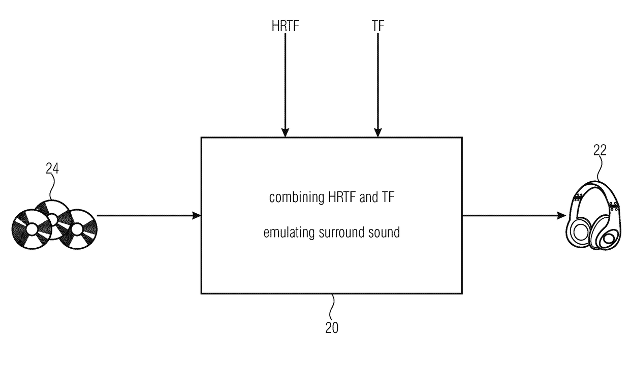
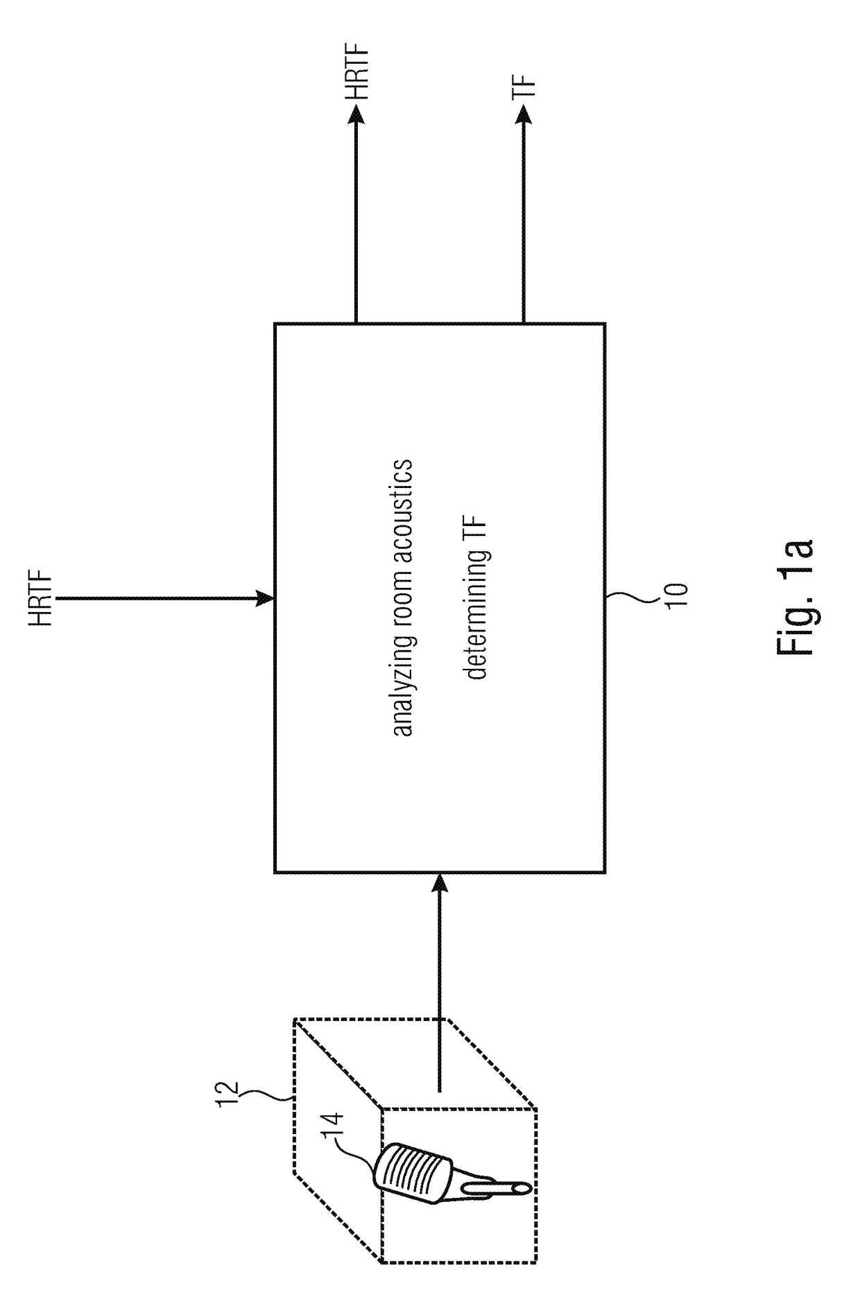
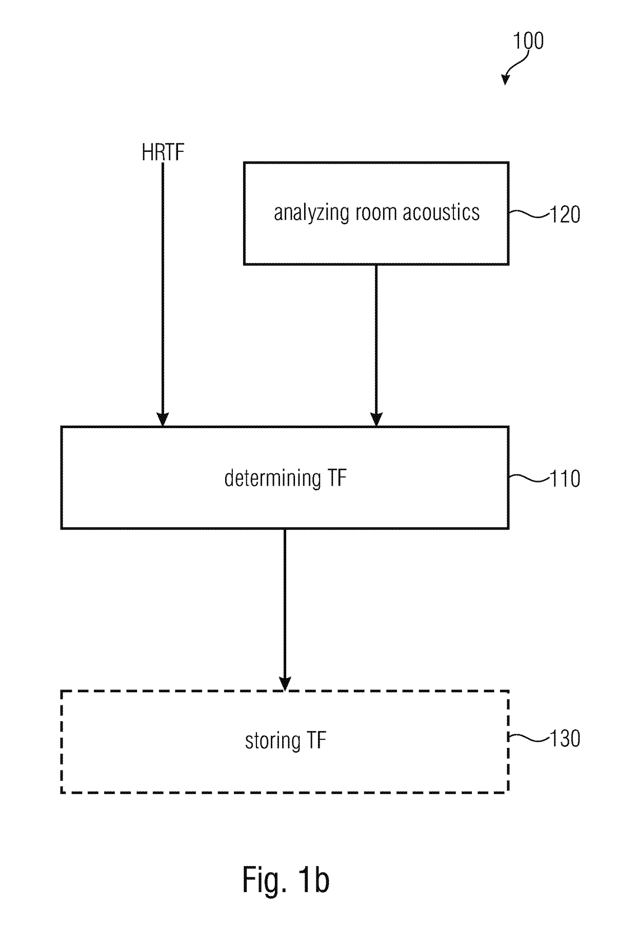
[0032]Before describing the invention, the motivation for detecting and auralizing the room acoustics of a listening room for a location-dependent spatial sound reproduction using headsets will be discussed. In this context, binaural synthesis will be explained briefly and there will be an overview of the head-related transfer functions (HRTFs) used for binaural synthesis and variations contained in the head-related transfer functions, which may be manipulated. Using this overview, it is also shown how the HRTFs are adapted by the room-optimized transfer functions TF to be determined in order to consider the room acoustics conditions in accordance with the invention.

[0033]Bin...


PUM


Abstract

A device for determining room-optimized transfer functions for a listening room serving for room-optimized post-processing of audio signals in spatial production, is configured to analyze room acoustics of the listening room and to determine, based on the analysis of the room acoustics, the room-optimized transfer functions for the listening room where the spatial reproduction by means of a binaural close-range sound transducer is to take place. The spatial reproduction of the audio signals by means of the binaural close-range sound transducer may then be emulated using known head-related transfer functions und using the room-optimized transfer functions, wherein a room to be synthesized may be emulated based on the head-related transfer functions, and wherein the listening room may be emulated based on the room-optimized transfer functions.

Description

CROSS-REFERENCE TO RELATED APPLICATIONS[0001]This application is a continuation of copending International Application No. PCT / EP2015 / 060792, filed May 15, 2015, which is incorporated herein by reference in its entirety, and additionally claims priority from German Application No. 10 2014 210 215.4, flied May 28, 2014, which is also incorporated herein by reference in its entirety.BACKGROUND OF THE INVENTION[0002]Embodiments of the present invention relate to a device for determining “room-optimized transfer functions” for a listening room, to a corresponding method and to a device for spatially reproducing an audio signal using corresponding methods. In accordance with preferred embodiments, reproduction takes place by means of a binaural close-range sound transducer, such as, for example, by means of a stereo headset or stereo in-ear earphones. Further embodiments relate to a system comprising the two devices, and to a computer method for performing the methods mentioned.[0003]The...

Claims


Application Information

Patent Timeline
IPC IPC(8): H04S7/00
CPCH04S7/306H04S2420/01H04S7/301H04R3/00H04R2430/00H04S7/304H04S2400/11
Inventor BRANDENBURG, KARLHEINZWERNER, STEPHANSLADECZEK, CHRISTOPH
Owner FRAUNHOFER GESELLSCHAFT ZUR FOERDERUNG DER ANGEWANDTEN FORSCHUNG EV
Why Eureka
Try Eureka