

Vaginal ring sensor
a vaginal ring and sensor technology, applied in the field of vaginal ring sensors, can solve the problems of not allowing the flow of vaginal fluid through the hole, and accommodating risks of surgery
- Summary
- Abstract
- Description
- Claims
- Application Information
AI Technical Summary
Benefits of technology
Problems solved by technology
Method used
Image

Examples
first embodiment
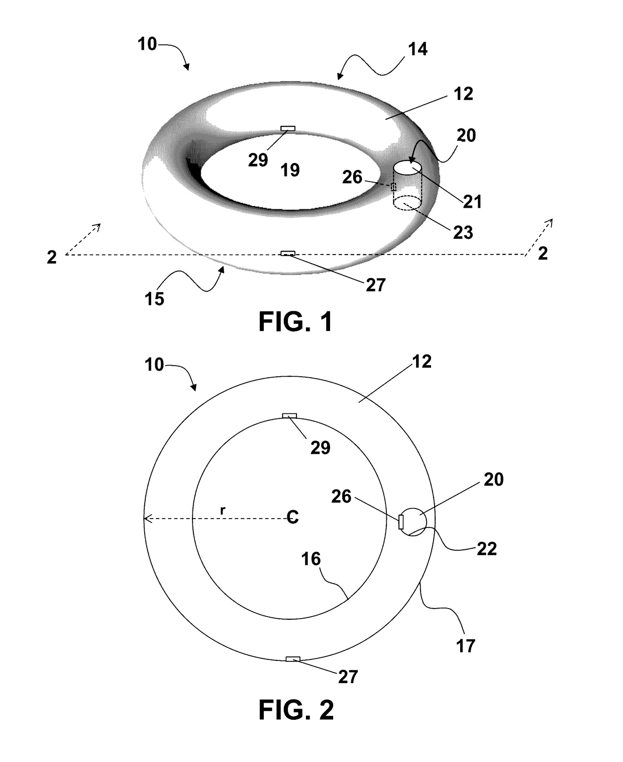
[0017]Biosensors inserted within the human body can be used to sense biomarker information via a wet interface within the body. One area inside the body with wet interfaces is within the vaginal vault. There are many fluids within the vaginal vault that can be used for wet interface sensing. Some of these fluids include vaginal transudate, Bartholin's and Skene's glands secretions, cervical mucus, exfoliated epithelial cells, and fluid from the uterus and endometrial tubes. The vaginal ring sensor device of the present invention is adapted to sense biomarker information via the wet interface located within the vaginal vault. a vaginal ring sensor device 10 according to the present invention is shown in FIGS. 1 and 2. The vaginal ring sensor device 10 includes a ring body 12 having a first surface 14 and a second surface 15. Second surface 15 is opposite first surface 14, and first surface 14 and second surface 15 may also be referred to as top 14 and bottom 15 surfaces, respectively...
second embodiment
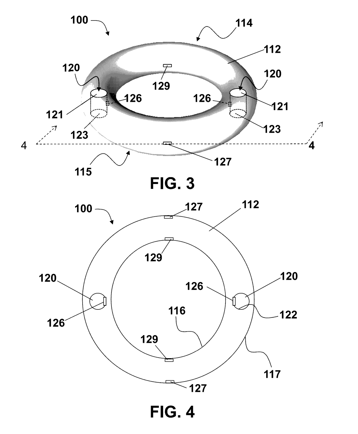
[0026]a vaginal ring sensor device 100 according to the present invention is shown in FIGS. 3 and 4. FIGS. 3 and 4 show a vaginal ring sensor device 100 having a plurality of through holes 120, and more particularly in the specific embodiment depicted, two through holes 120. Other embodiments of vaginal ring sensor device 100 of the present invention may include any suitable number of through holes 120, for example at least three, four, six, twelve, sixteen, twenty-four, or any number of through holes 120 as desired for the particular application of the invention.
[0027]FIGS. 3 and 4 depict each of the through holes 120 as having a round, or circular shape. However the through holes 120 may be structured and arranged to have other shapes. For example, the through holes 120 may be structured to be oval, race track, triangular, square, rectangular, rounded rectangle, or any other suitable shape that readily permits fluid to pass through the ring body 112 immediately upon insertion of t...
third embodiment
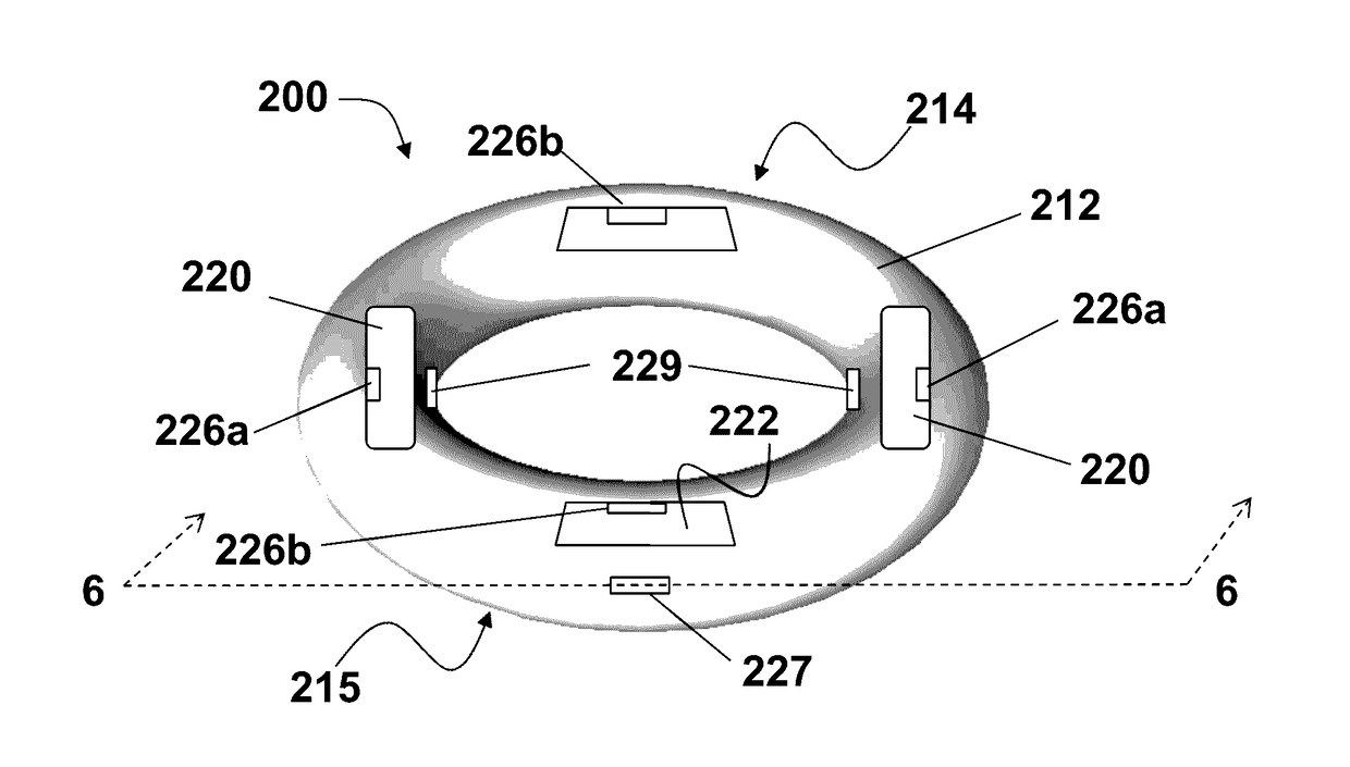
[0032]a vaginal ring sensor device 200 according to the present invention is shown in FIGS. 5 and 6. FIGS. 5 and 6 show a vaginal ring sensor device 200 having a plurality of through holes 220, and more particularly in the specific embodiment depicted four through holes 220. Other embodiments of vaginal ring sensor device 200 of the present invention may include any suitable number of through holes 220, for example six, twelve, sixteen, twenty-four, or any number of through holes 220 as desired for the particular application of the invention.
[0033]FIGS. 5 and 6 depict each of the through holes 220 as having a rounded rectangular shape. However the through holes 220 may be structured and arranged to have other shapes. For example, the through holes 220 may be structured to be oval, race track, square, rectangular, or any other suitable shape that readily permits fluid to pass through the ring body 212 immediately upon insertion of the device 200 into the vaginal vault and throughout ...
PUM
 Abstract
Description
Claims
Application Information