Method for repairing an airfoil, and cooling collar

a technology for airfoils and cooling collars, which is applied in the direction of turbines, machines/engines, manufacturing tools, etc., can solve the problems of airfoils of axial turbomachines, such as the rotor blades of gas turbines, being exposed to very high temperatures, and being unable to prevent wear of airfoils, etc., to achieve good contact and good heat transfer

Inactive Publication Date: 2017-03-23
SIEMENS AG
View PDF0 Cites 1 Cited by
  • Summary
  • Abstract
  • Description
  • Claims
  • Application Information

AI Technical Summary

Benefits of technology

[0007]Another aspect relates to a method of the type mentioned in the introduction, which is characterized in that the airfoil is cooled during the deposition welding. A significant advantage of such cooling during the deposition welding consists in the fact that the heat introduced into the component by the welding process is dissipated quickly, and this leads to very constant process conditions. In addition, it is possible to avoid idle periods between the welding of welded layers arranged one on top of another.
[0019]The housing is preferably provided with a clamping device, which is formed in such a manner that it presses the cooling elements against the object to be cooled in the intended state. Firstly, this ensures a good transfer of heat between the cooling elements and the object to be cooled. Secondly, the cooling collar can be pushed onto an object to be cooled and then fixed firmly thereto with the activation of the clamping device.

Problems solved by technology

During operation, airfoils of axial turbomachines, such as for example the rotor blades of gas turbines, are often exposed to very high temperatures and high levels of thermal loading.
In spite of such high-strength materials, however, it is not possible to prevent wear to the airfoils as a result of oxidation, thermal fatigue cracking, metal erosion or the like.
One problem in the case of known repair methods consists in the fact that the deposition welding introduces heat into the airfoil to be repaired, as a result of which residual welding stresses are brought about in the component; these can lead inter alia to cracks.
A further problem of known repair methods consists in the fact that, if a plurality of material layers are to be applied one on top of another, the previously generated material layer first has to cool down in order to keep the process conditions constant, and this is associated with long idle periods.

Method used


Image

  • Method for repairing an airfoil, and cooling collar
  • Method for repairing an airfoil, and cooling collar
  • Method for repairing an airfoil, and cooling collar

Examples


Embodiment Construction

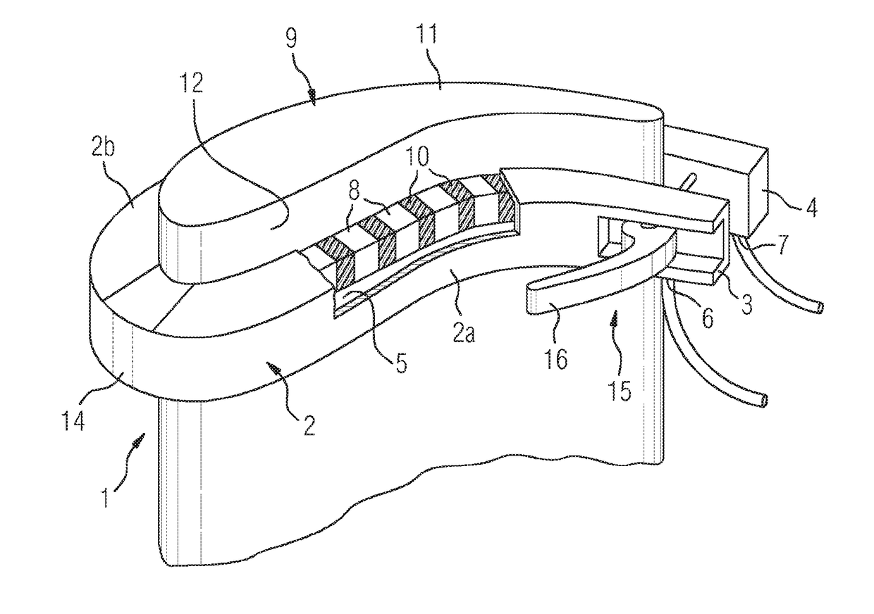
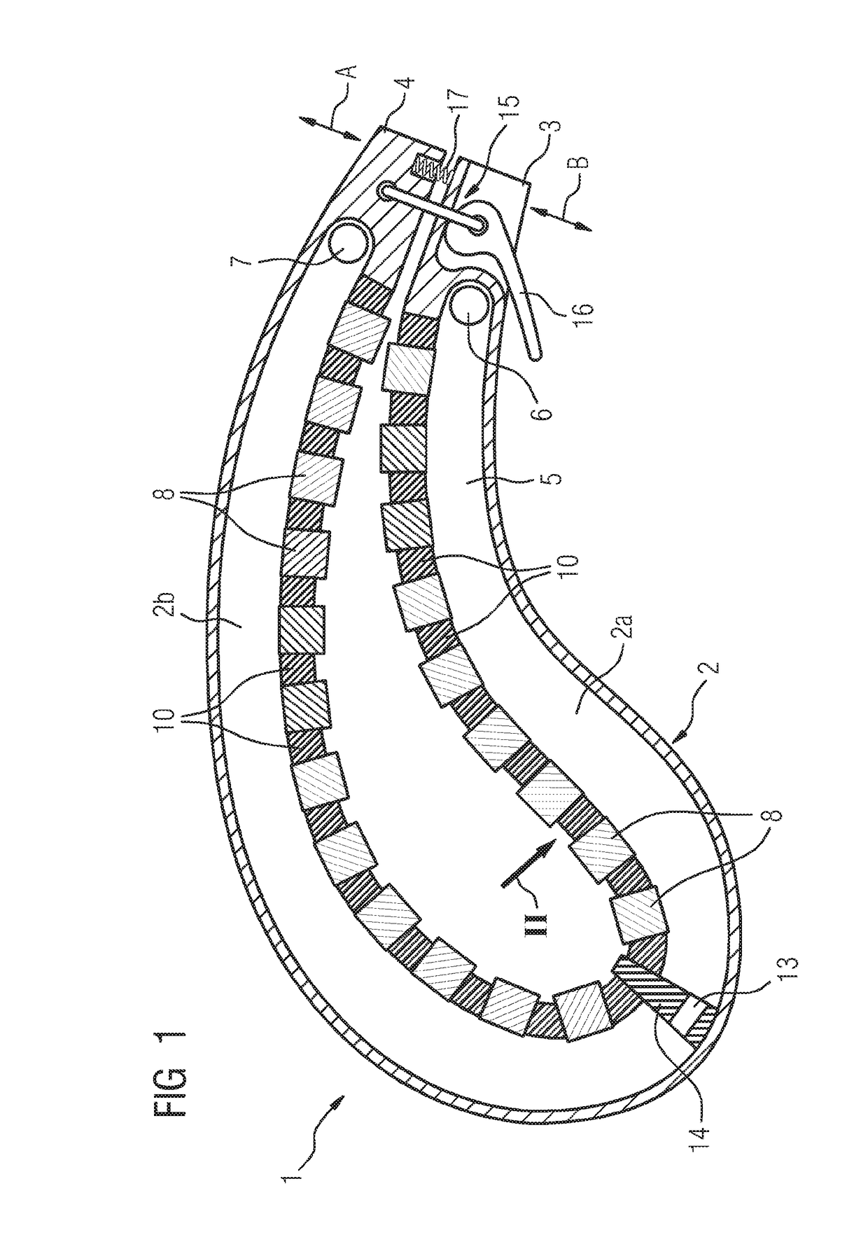
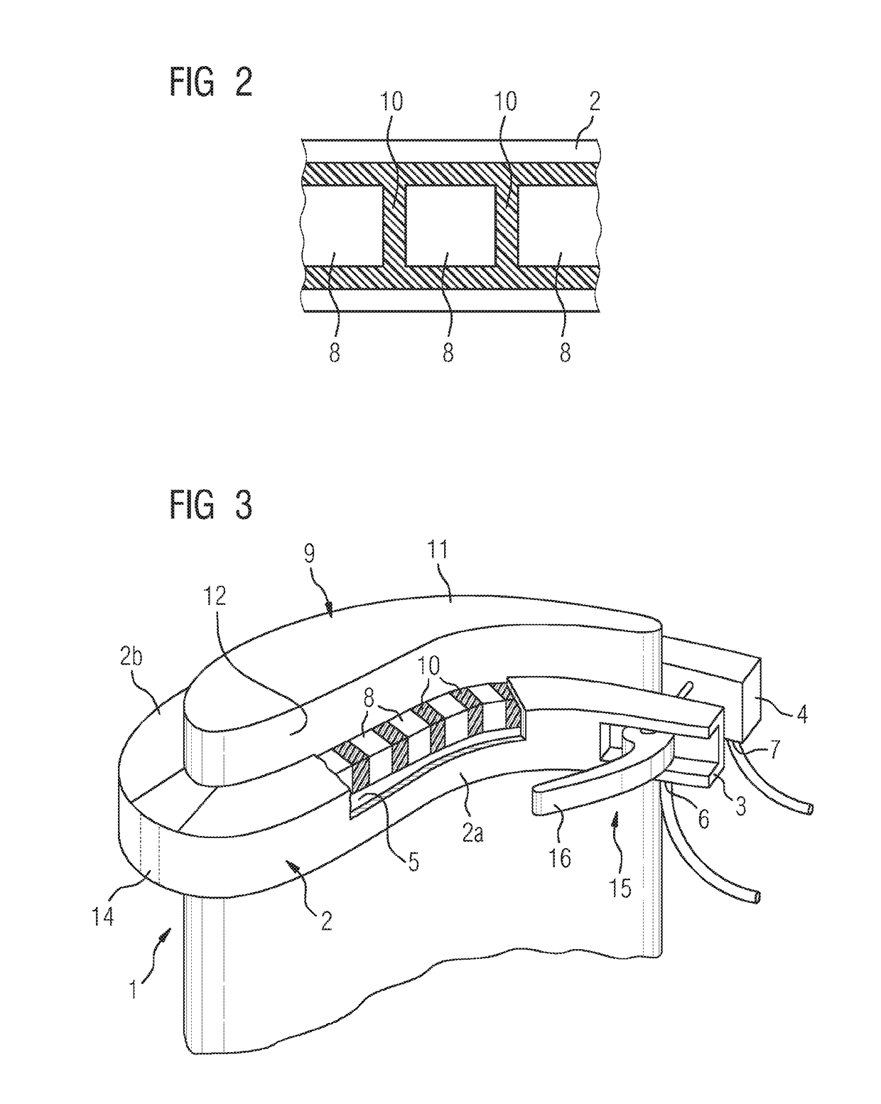
[0025]The Figures show a cooling collar 1 according to one embodiment of the present invention. The cooling collar 1 comprises an elongate housing 2 extending like a kidney and with mutually opposing free housing ends 3 and 4. A cooling channel 5 extends in the housing 2 and is provided with a coolant inlet 6 at one free housing end 3 and with a coolant outlet 7 at the other free housing end 4. The cooling collar 1 furthermore comprises a plurality of cooling elements 8, which are arranged along an inner wall of the cooling collar 1 and adjoining the cooling channel 5 and, in the intended state, rest against an airfoil 9 of a turbomachine, as will be explained in even more detail hereinbelow.

[0026]The cooling elements 8 are produced from a metallic material, in particular from aluminum, which is distinguished by its good thermal conductivity. Flexible sealing elements 10 are arranged between the respective cooling elements 8 and on the one hand seal off the intermediate spaces betwe...


PUM

PropertyMeasurementUnit
flexibleaaaaaaaaaa
shapeaaaaaaaaaa
temperaturesaaaaaaaaaa

Abstract

A method for repairing an airfoil of an axial turbomachine in which material is deposited onto the airfoil by means of deposition welding, the airfoil being cooled during the deposition welding, is provided. A cooling collar including at least one cooling channel which has a coolant inlet and a coolant outlet and through which a coolant flows in the intended state, is also provided. The cooling collar also includes multiple cooling elements which are arranged along an inner circumference of the cooling collar and adjacently to the at least one cooling channel, the cooling elements resting against an object to be cooled, in particular an airfoil to be cooled, in the intended state.

Description

CROSS-REFERENCE TO RELATED APPLICATIONS[0001]This application claims priority to PCT Application No. PCT / EP2015 / 059166, having a filing date of Apr. 28, 2015, based off of DE Application No. 102014209847.5 having a filing date of May 23, 2014, the entire contents of which are hereby incorporated by reference.FIELD OF TECHNOLOGY[0002]The following relates to a method for repairing an airfoil of an axial turbomachine, in which material is applied to the airfoil by means of deposition welding.BACKGROUND[0003]During operation, airfoils of axial turbomachines, such as for example the rotor blades of gas turbines, are often exposed to very high temperatures and high levels of thermal loading. For this reason, airfoils are produced from high-strength materials, such as for example from a nickel-based superalloy. In spite of such high-strength materials, however, it is not possible to prevent wear to the airfoils as a result of oxidation, thermal fatigue cracking, metal erosion or the like....

Claims


Application Information

Patent Timeline
Patent Type & Authority Applications(United States)
IPC IPC(8): B23P6/00F01D9/02F01D5/00F01D5/12B23K26/342B23K26/70
CPCB23P6/002B23K26/342B23K26/703F01D5/005F05D2240/307F01D9/02B23K2201/001F05D2230/80F05D2240/125F01D5/12B23P6/007F05D2230/232B23K2101/001
Inventor ARJAKINE, NIKOLAIBOSTANJOGLO, GEORGBURBAUM, BERNDKALOCSAY, ROMAN
Owner SIEMENS AG
Why Eureka
Try Eureka