
Systems and methods for distillation of water from seawater, brackish water, waste waters, and effluent waters

a technology of waste water and effluent water, which is applied in the field of water purification, can solve the problems of brine being toxic to the marine environment in the surrounding area, affecting the quality of water supply, and increasing the cost of methods, so as to minimize heat loss and minimize heat loss

Active Publication Date: 2017-03-23
GLOBAL WATER FARMS CORP
View PDF0 Cites 5 Cited by
  • Summary
  • Abstract
  • Description
  • Claims
  • Application Information

AI Technical Summary

Benefits of technology

The patent describes a method of carrying out steps in a way that reduces heat loss. This can be done by using a super-insulated structure made of concrete or steel. The technical effect is that this method can help to minimize the amount of heat that is lost during the steps.

Problems solved by technology

These methods can be expensive; typically, large-scale RO systems produce clean water at a cost of between $1.50 and $2.00 per cubic meter, and MED systems produce clean water a cost of $0.70 and $1.50 per cubic meter.
As a result, small or cash-strapped communities are often unable to pursue desalination to meet their needs for clean water and are forced to rely on other sources, which may have more pronounced environmental consequences.
In addition, RO and MED themselves have a number of environmental and economic drawbacks.
Many RO and MED plants emit concentrated brine as a waste product; this brine can be toxic to the marine environment in the surrounding area.
RO and MED systems are also notoriously fragile and unreliable, and often shut down even when only a single part fails.
RO has a particularly strong negative effect on environment because it relies on filter membranes, the manufacture of which creates industrial wastes, and requires significant quantities of electrical power.
MED uses less electrical power than RO, but requires a steam source in addition to an electrical source; many methods of generating steam have severe environmental impacts.

Method used


Image

  • Systems and methods for distillation of water from seawater, brackish water, waste waters, and effluent waters
  • Systems and methods for distillation of water from seawater, brackish water, waste waters, and effluent waters
  • Systems and methods for distillation of water from seawater, brackish water, waste waters, and effluent waters

Examples


Embodiment Construction

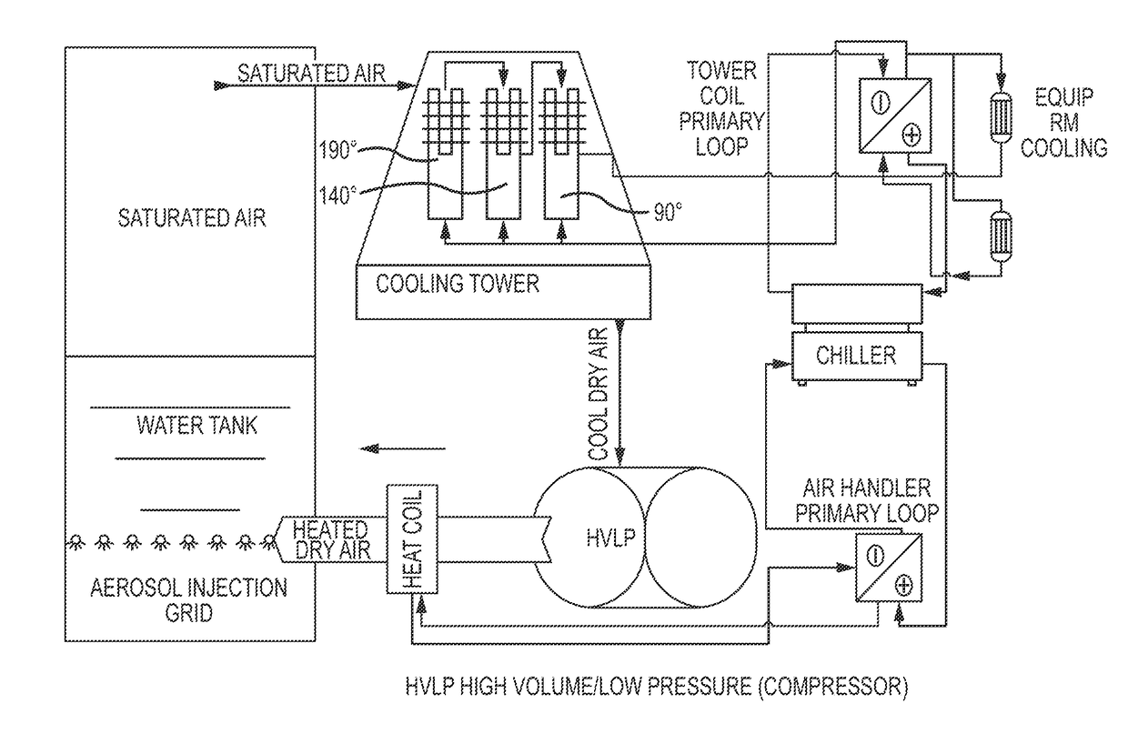
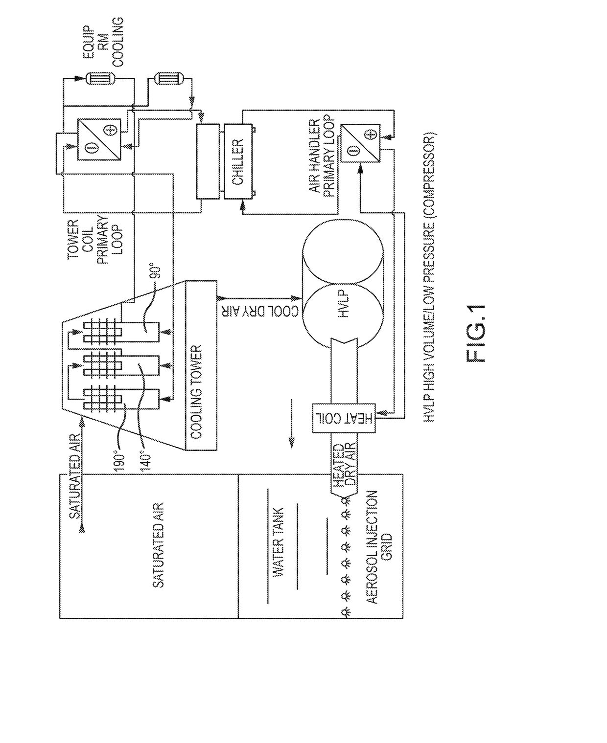
[0006]It is one aspect of embodiments of the present invention to provide a system for purifying water, comprising a solar energy collection device, collecting solar energy and heating a heat transfer fluid in a heat exchanger, the heat exchanger receiving and heating non-potable water; a super-insulated structure; a distilled water reservoir; and a concentrated effluent reservoir. The super-insulated structure comprises a distillation tower, receiving the heated non-potable water; a high-volume low-pressure (HVLP) blower, compressing intake air to form compressed air having a temperature of between about 208° F. and about 210° F., and injecting the compressed air into the distillation tower to form saturated air and a concentrated effluent in the distillation tower, wherein the compressed air enters the distillation tower via a plurality of microbubble nozzles located at a vertical midpoint of a water column comprising the heated non-potable water and the concentrated effluent; a c...


PUM

PropertyMeasurementUnit
temperatureaaaaaaaaaa
boiling pointaaaaaaaaaa

Abstract

The present invention relates to water purification using solar energy. More specifically, systems and methods according to the present invention collect solar energy to heat non-potable water in a super-insulated structure. Compressed heated air is injected to evaporate water vapor out of brackish water, saltwater, or dirty water, thereby creating saturated air. The saturated air is drawn through a cooling tower and distilled water is precipitated. The systems and methods employ heat recovery and recycling processes to maximize energy efficiency.

Description

CROSS REFERENCE TO RELATED APPLICATION[0001]This application claims the benefit of U.S. Provisional Patent Application 62 / 209,277, filed 24 Aug. 2015, the entirety of which is incorporated herein by reference.FIELD OF THE INVENTION[0002]The present invention relates to water purification, and more specifically to the distillation of brackish water, saltwater, or dirty water using solar energy.BACKGROUND OF THE PRESENT INVENTION[0003]Currently, the two main methods known for water desalination are reverse osmosis (RO) and multiple effect distillation (MED). These methods can be expensive; typically, large-scale RO systems produce clean water at a cost of between $1.50 and $2.00 per cubic meter, and MED systems produce clean water a cost of $0.70 and $1.50 per cubic meter. As a result, small or cash-strapped communities are often unable to pursue desalination to meet their needs for clean water and are forced to rely on other sources, which may have more pronounced environmental conse...

Claims


Application Information

Patent Timeline
Patent Type & Authority Applications(United States)
IPC IPC(8): C02F1/04B01D1/00B01D1/14C02F1/10B01D5/00C02F1/14C02F1/16B01D3/00B01D3/16
CPCC02F1/048B01D3/007B01D1/0041B01D1/0058B01D1/14B01D3/16C02F2303/10B01D5/006C02F1/14C02F1/16B01D1/0035C02F1/10C02F2103/08B01D5/0006Y02A20/00Y02A20/124Y02A20/211Y02A20/212Y02P70/10Y02W10/30Y02W10/37
Inventor BECKER, JONATHAN
Owner GLOBAL WATER FARMS CORP
Learn More