Engine device

a technology of engine and exhaust, which is applied in the direction of machines/engines, combustion-air/fuel-air treatment, electric control, etc., can solve the problems of affecting environmental preservation and large number of exhaust emissions, and achieve the elimination or minimization of the amount of air needed for combustion, the effect of increasing trackability

Inactive Publication Date: 2017-03-23
YANMAR POWER TECHNOLOGY CO LTD
View PDF5 Cites 1 Cited by
  • Summary
  • Abstract
  • Description
  • Claims
  • Application Information

AI Technical Summary

Benefits of technology

[0013]According to the embodiment of the present invention, in a state in which the supercharger is optimized in accordance with a combustion mode specification for liquid fuel, in a combustion mode using gas fuel, control of each of the opening degree of the exhaust bypass valve and the opening degree of the air supply bypass valve in accordance with the variation of an engine load also realizes an air-fuel ratio optimized to the engine load. With this configuration, therefore, during a load variation, the deficiency of the amount of air needed for the combustion is eliminated or minimized, and as a result, the engine device operates optimally in the gas mode in a state in which the supercharger is optimized for use in in the diesel mode is used.
[0014]Further, feedback control on the air supply bypass valve and map control on the exhaust bypass valve that are concurrently performed realize supplying the engine device with air adapted to an air-fuel ratio needed for the combustion of the gas fuel. Control of the opening degree of the air supply bypass valve in accordance with the variation of an engine load realizes supplying the engine with air adapted to an air-fuel ratio needed for the combustion of the gas fuel. Further, a combination with responsive control operation by the air supply bypass valve increases trackability relative to a load variation in the gas mode. Moreover, control of air pressure by both of the air supply bypass valve and the exhaust bypass valve realizes expansion of a control range of the control of air pressure.
[0015]Further, within the low load range, when the engine load is higher than a predetermined load, feedback control on the air supply bypass valve and map control on the exhaust bypass valve are concurrently performed, and thus, the responsiveness of flow amount control by the air supply bypass valve and constant amount control by the exhaust bypass are complemented each other, and control range of the air supply bypass valve is complemented by the exhaust bypass valve. Moreover, in the case where the engine load is lower than the predetermined load, even when air pressure inside the intake manifold becomes negative during a low load operation, concurrent control of causing the exhaust bypass valve to fully open and of causing the air supply bypass valve to be fully closed realizes securing an air amount needed for the combustion.
[0016]Further, according to the embodiment of the present invention, within the low load range, when the engine load is lower than the predetermined load, the feedback control is performed on the main throttle valve, whereas, when the engine load is higher than the predetermined load, the map control based on the data table is performed on the main throttle valve. Thus, in a state in which the supercharger is optimized in accordance with a combustion mode specification for liquid fuel, in a combustion mode using gas fuel, control of each of the opening degree of the exhaust bypass valve and the opening degree of the air supply bypass valve in accordance with the variation of an engine load also realizes an air-fuel ratio optimized to the engine load. With this configuration, therefore, during a load variation, the deficiency of the amount of air needed for the combustion is eliminated or minimized, and as a result, the engine device also operates in a suitable condition in the gas mode in a state in which the supercharger optimized for use in the diesel mode is used.
[0017]Further, within the low load range, when the engine load is higher than the predetermined load, feedback control on the exhaust bypass valve and map control on the air supply bypass valve are concurrently performed, and thus, the responsiveness of flow amount control by the exhaust bypass valve is complemented by the air supply bypass valve, and control range of the air supply bypass valve is complemented by the exhaust bypass valve. Moreover, within the low load range, in the case where the engine load is lower than the predetermined load, even when air pressure inside the intake manifold becomes negative during a low load operation, concurrent control of causing the exhaust bypass valve to fully open and of causing the air supply bypass valve to be fully closed realizes securing an air amount needed for the combustion.
[0018]Further, within the medium and high load range, feedback control on the air supply bypass valve and map control on the exhaust bypass valve that are concurrently performed realize supplying the engine device with air adapted to an air-fuel ratio needed for the combustion of the gas fuel. Control of the opening degree of the exhaust bypass valve in accordance with the variation of an engine load realizes supplying the engine with air adapted to an air-fuel ratio needed for the combustion of the gas fuel. Further, a combination with responsive control operation by the air supply bypass valve increases trackability relative to a load variation in the gas mode. Moreover, control of air pressure by both of the air supply bypass valve and the exhaust bypass valve realizes expansion of a control range of the control of air pressure.

Problems solved by technology

Exhaust gas discharged from such a diesel engine, unfortunately, contains a large number of exhaust emissions, such as oxides of nitrogen, oxides of sulfur, and particulate matter, that are likely to become harmful substances that impede environmental preservation.

Method used


Image

  • Engine device
  • Engine device
  • Engine device

Examples


Embodiment Construction

[0041]Hereinafter, an embodiment resulting from embodying the present invention will be described on the basis of figures when this embodiment is applied to a pair of propulsion and power-generation mechanisms mounted in a ship of a twin-engine and twin-shaft type.

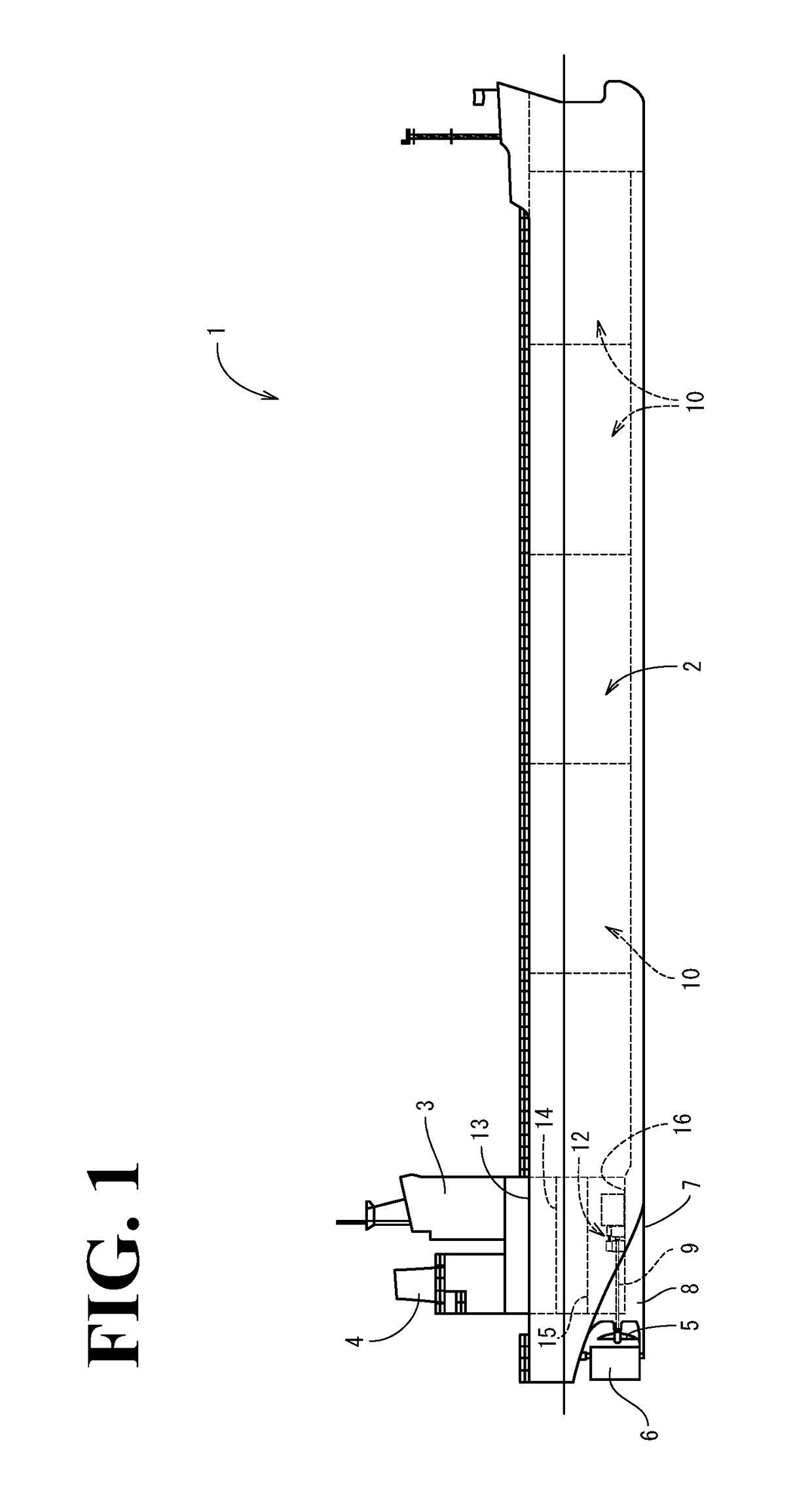
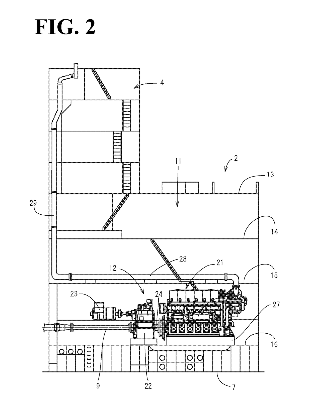
[0042]First, the outline of a ship will be described. As illustrated in FIGS. 1 to 3, a ship 1 according to this embodiment includes a hull 2, a cabin 3 (a bridge deck), a funnel 4 (a smoke stack), a pair of propellers 5, and a rudder 6. The cabin 3 is disposed at the aft side of the hull 2. The funnel 4 is disposed behind the cabin 3. The pair of propellers 5 and the rudder 6 are disposed in a lower portion of the rear side of the hull 2. In this case, a pair of skegs 8 are formed integrally with an aft portion of a bottom 7. Propulsion shafts 9 are each rotatably supported by a corresponding one of the skegs 8. The propulsion shafts 9 each drivingly rotate a corresponding one of the propellers 5. The slegs 8 are formed i...


PUM


Abstract

When a load on an engine device is lower than a first predetermined load falling within a low load range, feedback control is performed on a main throttle valve. When the load is higher than the first predetermined load, map control based on a data table is performed on the main throttle valve. When the load is higher than a second predetermined load higher than the first predetermined load, an opening degree of the main throttle valve is brought to a fully-open opening degree, and each of an exhaust bypass valve and an air supply bypass valve is controlled to allow pressure inside an intake manifold to be adjusted to a target value appropriate to the load.

Description

CROSS-REFERENCE TO RELATED APPLICATIONS[0001]The present application is a continuation application of International Application No. PCT / JP2015 / 065454, filed May 28, 2015, which claims priority to Japanese Patent Application No. 2014-118035, filed Jun. 6, 2014, Japanese Patent Application No. 2014-251243, filed Dec. 11, 2014. The contents of these applications are incorporated herein by reference in their entirety.BACKGROUND OF THE INVENTION[0002]The present invention relates to an engine device.[0003]Heretofore, in ships, such as a tanker and a transport ship, and land-based power generation facilities, diesel engines have been used as their driving sources. Exhaust gas discharged from such a diesel engine, unfortunately, contains a large number of exhaust emissions, such as oxides of nitrogen, oxides of sulfur, and particulate matter, that are likely to become harmful substances that impede environmental preservation. For this reason, recently, a gas engine, one of engines each ser...

Claims


Application Information

Patent Timeline
Patent Type & Authority Applications(United States)
IPC IPC(8): F02D41/00F02D9/02F01N13/10F02M35/104F02B37/18F02B43/04
CPCF02D41/0007F02B37/18F02B43/04F02D2200/1002F02M35/104F02D9/02F01N13/10F02B37/16F02B43/00F02D19/06F02D19/0642F02D23/00F02D41/1401F02D41/3094F02D2041/141F02D2200/0406Y02T10/12Y02T10/30F02B37/12
Inventor HIROSE, KOICHIMURAKAMI, TAISHIOHSARA, TATSURO
Owner YANMAR POWER TECHNOLOGY CO LTD
Why Eureka
Try Eureka