
Integrated circuit arrangement for a position sensor

a position sensor and integrated circuit technology, applied in the direction of converting sensor output electrically/magnetically, instruments, measurement devices, etc., can solve the problems of no absolute optical rotation counter, sensitive optical angle sensors with respect, etc., and achieve the effect of loss of output signal precision

Active Publication Date: 2017-03-30
AVAGO TECH INT SALES PTE LTD
View PDF12 Cites 2 Cited by
  • Summary
  • Abstract
  • Description
  • Claims
  • Application Information

AI Technical Summary

Benefits of technology

This patent is about a new arrangement of Hall elements on a triangular or quadrangular measurement substrate for a position sensor. This arrangement can increase the precision of the sensor without using a field concentrator and achieve strong output signals from the Hall elements. It also reduces the influence of field inhomogeneities caused by temperature variations of the permanent magnet. The controller, which processes the output signals of the Hall elements, can accelerate the object being monitored and calculate the absolute position of the magnet within a very short time. In the case of a position sensor that detects rotations of the magnet, the field concentrator can rotate together with the magnetic field to avoid hysteresis jumps.

Problems solved by technology

However, optical angle sensors are sensitive with respect to dirt of all kinds and are applicable only in a limited temperature range.
Moreover, there are no absolute optical rotation counters, which can do without battery or gearing mechanism for the absolute counting.

Method used


Image

  • Integrated circuit arrangement for a position sensor
  • Integrated circuit arrangement for a position sensor
  • Integrated circuit arrangement for a position sensor

Examples


Embodiment Construction

[0054]It should be noted that the term “comprising” does not exclude other elements or steps and the “a” or “an” does not exclude a plurality. Also elements described in association with different embodiments may be combined.

[0055]It should also be noted that reference signs in the claims shall not be construed as limiting the scope of the claims.

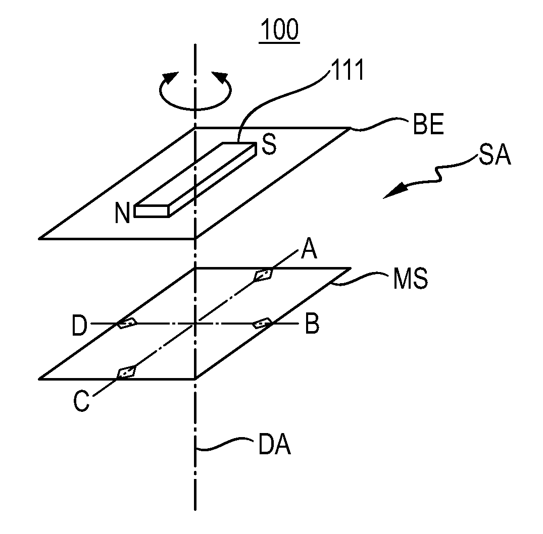
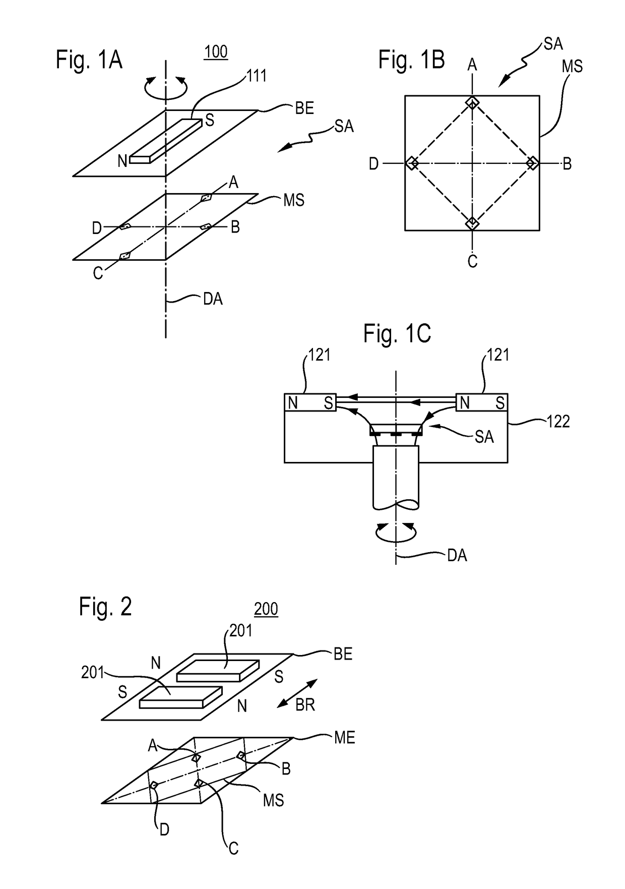
[0056]FIG. 1A illustrates schematically a position sensor 100 according to the invention, in particular an absolute fine position sensor according to the invention.

[0057]The position sensor 100 may comprise a permanent magnet 111, which may be pivot-mounted (or supported rotatably), wherein it may lie in a movement plane BE, such that its north pole N and its south pole S can rotate around a rotation axis DA. The movement plane BE of the permanent magnet 111 is drawn schematically in FIG. 1A, and may be perpendicular to the rotation axis DA.

[0058]Preferably, the permanent magnet 111 may be embodied as a rectangular-shaped bar magnet having ...


PUM


Abstract

The invention relates to an integrated circuit arrangement for a position sensor for measuring angles or distances, wherein the circuit arrangement comprises:a measurement substrate, which defines a measurement plane and which is configured such that it comprises a plurality of corners;at least three Hall elements, which are arranged on the measurement substrate such that areas of the Hall elements, which are sensitive to a magnetic field, extend in the measurement plane and / or form a part of the measurement plane, and that a virtual polygon, which is formed by the Hall elements, is rotated with respect to the measurement substrate such that the Hall elements are each located at an outer edge of the measurement substrate and have a distance to a center of an edge of the corresponding outer edge amounting to at maximum 25% of a total length of the corresponding outer edge, whereinthe Hall elements are, in an intended use of the circuit arrangement during the measurement, configured to respectively output an output signal, which corresponds to a magnetic field strength of a magnet to be detected; anda processing electronic system, to which the output signals of the Hall sensors are delivered in the intended use of the circuit arrangement during the measurement.

Description

CROSS-REFERENCE TO RELATED APPLICATIONS[0001]The present application claims the priorities of the German patent application no. DE 10 2015 218 651, filed Sep. 28, 2015, and of the German patent application no. DE 10 2015 117 067, filed Oct. 7, 2015, which are both incorporated herein by reference in their entirety.FIELD OF THE INVENTION[0002]The present invention relates to an integrated circuit arrangement for a position sensor, in particular for a position sensor for measuring angles or distances.TECHNOLOGICAL BACKGROUND[0003]The optical angle sensors, which have been developed to a high quality in the last decades, dominate the market place today. Their advantage rests in the high speed, which is increasingly inevitable in drive technology, as well as in the matured technology.[0004]However, optical angle sensors are sensitive with respect to dirt of all kinds and are applicable only in a limited temperature range. Moreover, there are no absolute optical rotation counters, which ...

Claims


Application Information

Patent Timeline
Patent Type & Authority Applications(United States)
IPC IPC(8): G01D5/14
CPCG01D5/145
Inventor MEHNERT, WALTERTHEIL, THOMAS
Owner AVAGO TECH INT SALES PTE LTD
Learn More