Digital power plant system and method

a power plant and digital technology, applied in the field of power generation and distribution, can solve the problems of complex analysis of power plant data, collection and transmission, and owners of power plant fleets not having complete freedom to set the price of power they sell

Inactive Publication Date: 2017-03-30
GENERAL ELECTRIC CO
View PDF1 Cites 123 Cited by
  • Summary
  • Abstract
  • Description
  • Claims
  • Application Information

AI Technical Summary

Benefits of technology

[0017]A Digital Power Plant (DPP) has been invented and is disclosed herein. A DPP may be embodied as a cloud-based computer system that the models all power generation units, and other components and systems in a power plant. The DPP includes digital models of the sub-systems, such as gas turbines, of the power generation unit in a power plant. By modeling the various sub-systems in a power plant in a cloud-based computer system, the DPP can be operated as part of virtual fleets of power plants to provide information on how all power plants can be optimally operated. The DPP enables the power plant or fleet to act and behave optimally with respect to a larger environment of an entire power generation grid.
[0018]A goal of DPP is to enable harmonious data and control flow between existing systems not only for its day to day operations but also for extending the life of all assets while maximizing return on investment (ROI). The DPP interconnects systems that analyze power generation and shares data between these systems. The DPP sets a foundational system for seamless communication of data related to power generation and the sharing of intelligence and analytical tools.
[0019]The DPP can be thought of as a human body. A human body has independent organ systems which must be coordinated and operated as a single human body. Similarly, a power plant or fleet of plants is an independent organ system of a power grid that should operate in a coordinate manner with the entire grid. The organ systems of the human body shares information (nutrients and nerve signals) to coordinate the operation of one organ with respect to another and the entire body Similarly, the DPP shares information among power plants so that the operation of all plants may be coordinated.
[0022]The DPP is a system extends the data communication and analysis associated with a power plant to cloud computing. This extension enables for seamless data and control flow between the various sub-components in power generation units and fleets. Cloud computing also enables optimization of the operation of a power plant thru: prognostic recommendations; optimization of operations of different subsystems of a power plant independently or in concert; rapidly respond to changing market conditions; and sharing all of the knowledge and information relevant to power generation.
[0023]The DDP operates as one cohesive systems, where all digital models of power plants and individual power generating units within the plants, data and analytics are synchronized between the plants and the cloud based computing system. This enables the DPP to function as one unified system and allows for the overall operation of a site or sites to be optimized from the cloud and to apply learnings from across the fleet.

Problems solved by technology

The owners of fleets of power plants do not have complete freedom to set the price for power that they sell.
The analysis of this data is complex and is conventionally performed using various types of software analytical systems.
Collecting and transmitting data to the software analytical systems, generating the analyses and distributing the results of the analyses in a timely manner has proven difficult.
The generation of the offer curves may be made based on inadequate or imperfect knowledge of the market demand.
Offer curves may not be generated in a uniform manner or generated in a manner that does not optimize the performance of an individual power plant or the overall performance of all power plants.
Machine degradation in power generation units occurs over time and the degradation may have a significant effect on the performance of the generating units.
Hours-based life in a gas turbine may be prolonged by its reducing firing temperature, but this reduces efficiency of the gas turbine, which increases cost of operation.
Increasing the firing temperature increases efficiency shortens gas turbine life and increases maintenance and / or replacement costs.
Given the complexity of modern power plants, particularly those having multiple power generating units, and the market for power, power plant operators struggle to determine the operating settings for their power plant that will maximize economic return and minimize the degradation on the systems.

Method used


Image

  • Digital power plant system and method
  • Digital power plant system and method
  • Digital power plant system and method

Examples


Embodiment Construction

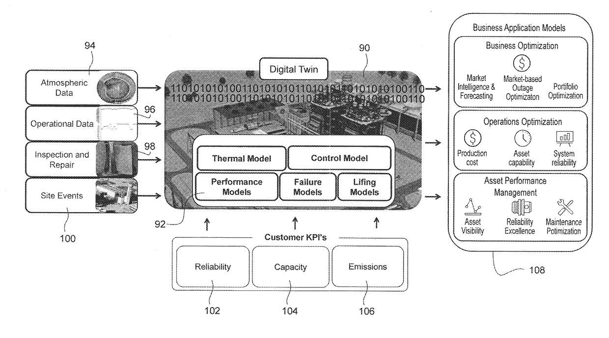
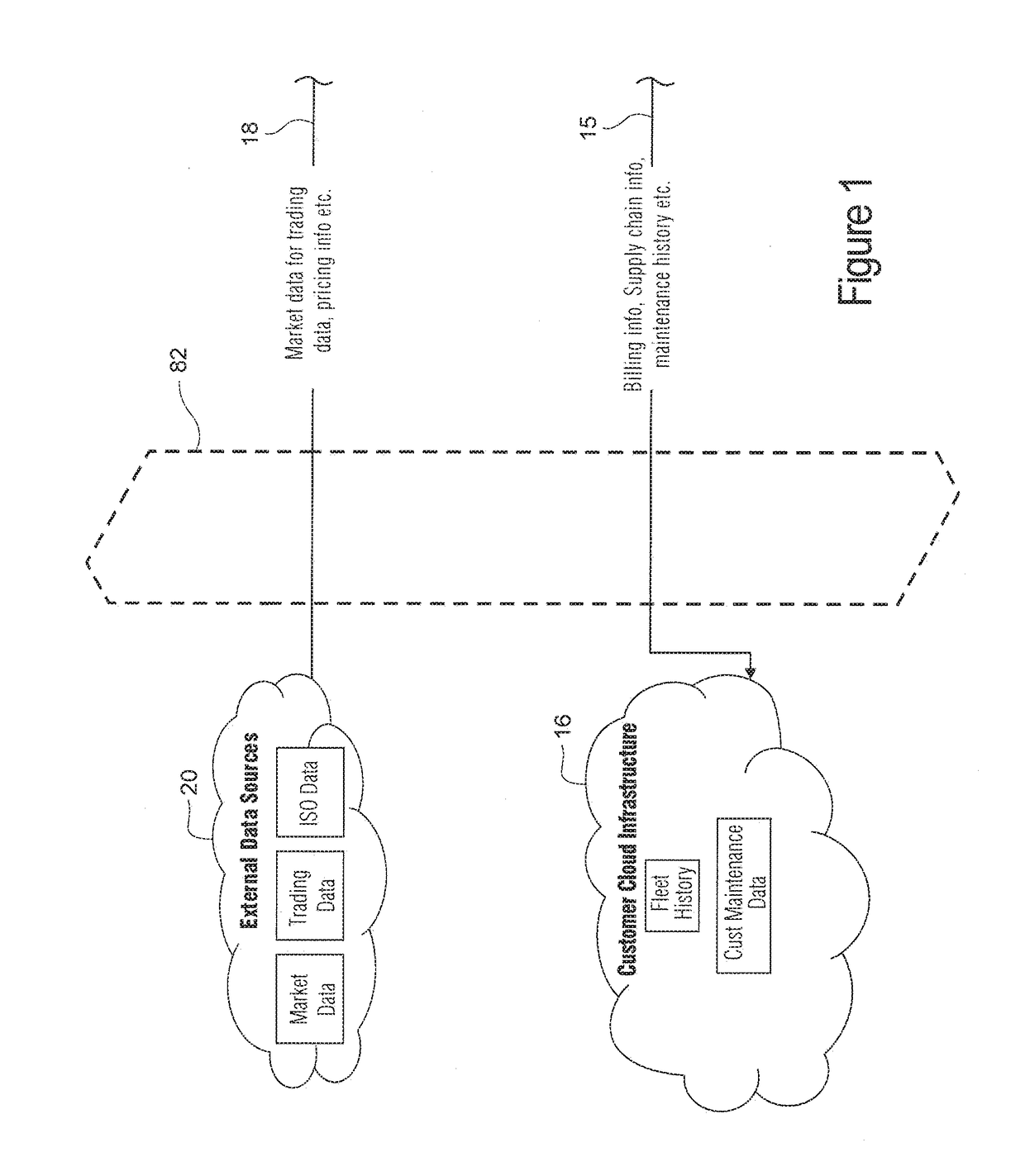
[0029]FIGS. 1 to 3 are a diagram a system for managing fleets of power generation plants or an individual facility and, particularly, for handing data needed to manage the fleets. The system includes a central cloud computing system 10 which collects data generated by individual power plants 12 which may be group in fleets 14 of power plants. Each fleet may be operated by a customer, such as a public utility or other entity that owns or operates power plants. Data 15 from the customer is collected from a customer computer system 16 by the central cloud computing system 10. In addition, data 18 about market conditions is collected from external data sources 20. The market condition data may indicate demand for power by end-use customers, such as office buildings, factories and residences, the amount and cost of power being generated and the availability and cost of fuels and other resources needed to operate the power plants in the fleets.

[0030]Customers of the system 10 may maintain...


PUM


Abstract

A Digital Power Plant (DPP) deployed on a cloud-based computer system that the enables all components and systems in a fleet of power plants. By digitally extending the various sub-systems in a power plant to the cloud-based computer system, the system enables the power plant or fleet to act and behave optimally with respect to a larger environment of an entire power generation grid.

Description

CROSS RELATED APPLICATION[0001]This application is a non-provisional of 62 / 233,296 filed Sep. 25, 2015, wherein the entire contents of this application is incorporated by reference.BACKGROUND OF THE INVENTION[0002]The invention relates generally to power generation and distribution over geographically large networks and, more particularly, to methods and systems related to performance optimization and operation of power plants and fleets of power plants.[0003]Electrical power is distributed through large networks, such as power grids, that transmit the power from power plant to power consuming customers, such as homes, factories and office buildings. An individual power plant may be operated in a fleet of commonly owned plants by a power generation company. Each fleet may be owned and operated by a different company. There may be many fleets of power plant and individually operated power plants that distribute electrical power through the power grid.[0004]Electrical power distribute...

Claims


Application Information

Patent Timeline
Patent Type & Authority Applications(United States)
IPC IPC(8): G06Q30/02G06N99/00G06F17/50G06N5/04H04L29/08H02J3/38G06N20/00
CPCG06Q30/0202H04L67/10H02J3/381H02J2003/007G06Q30/0201G06N5/04G06N99/005G06F17/5009Y04S50/14Y02B10/30Y04S10/12G06N20/00G06F30/20H02J2203/20H02J2300/10Y02E40/70Y02E60/00Y02P80/20Y04S40/20Y04S10/50G06N5/01
Inventor SRINIVASAN, JAYANTHICHOTAI, SHAM
Owner GENERAL ELECTRIC CO
Why Eureka
Try Eureka