Power-receiving device, wireless power-transmitting system, and power-transmission device

a power-receiving device and wireless technology, applied in the direction of transportation and packaging, emergency protective arrangements for limiting excess voltage/current, safety/protection circuits, etc., can solve the problems of power-transmission devices, power-receiving devices, and may be brought into an open state unintentionally, so as to prevent damage to the elements

Inactive Publication Date: 2017-03-30
IHI CORP
View PDF9 Cites 30 Cited by
  • Summary
  • Abstract
  • Description
  • Claims
  • Application Information

AI Technical Summary

Benefits of technology

[0012]According to the power-receiving device, the wireless power-transmitting system, and the power-transmission device of this disclosure, damage to the elements can be prevented.

Problems solved by technology

However, while a power-transmission device of the wireless power-transmitting system transmits power to the power-receiving device, the above switch may be brought into an open state unintentionally due to various factors, such as a malfunction.
Since power cannot be supplied to the battery if the transmission of power continues with the switch being open, the voltage inside the power-transmission device and the power-receiving device rises, an overvoltage is applied to elements that constitute the power-transmission device and the power-receiving device, and damage to the elements, the power-transmission device, and the power-receiving device may be caused.

Method used


Image

  • Power-receiving device, wireless power-transmitting system, and power-transmission device
  • Power-receiving device, wireless power-transmitting system, and power-transmission device
  • Power-receiving device, wireless power-transmitting system, and power-transmission device

Examples


first embodiment

[0019]Hereinafter, this disclosure will be described with reference to the drawings.

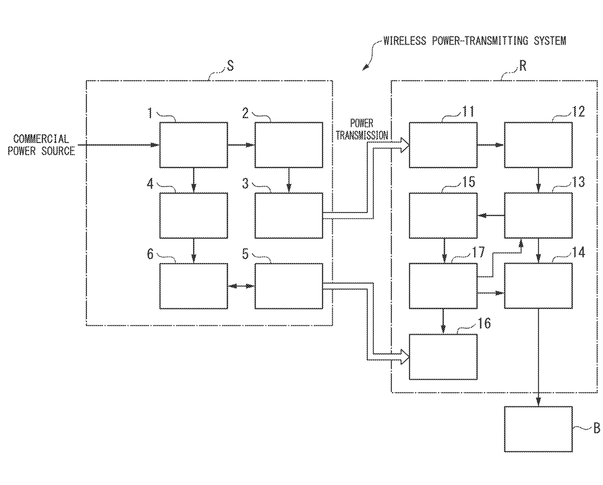
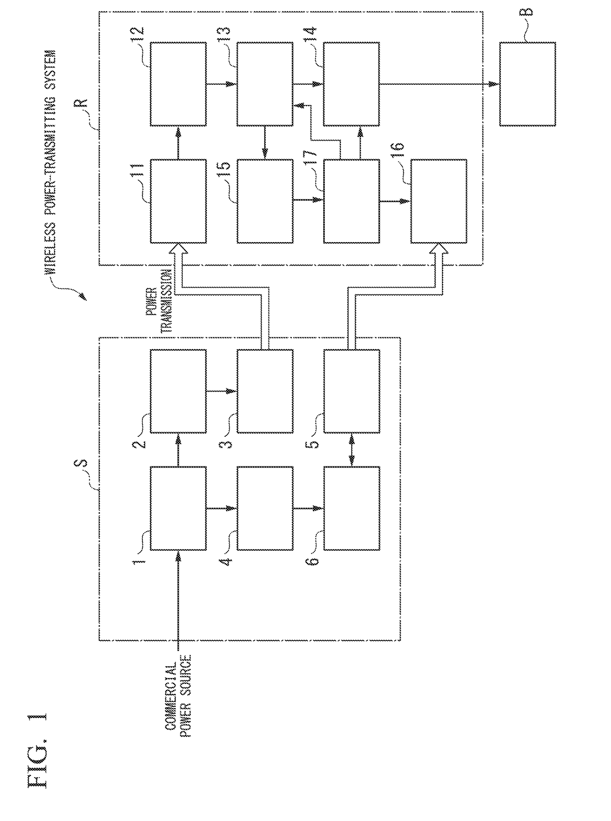
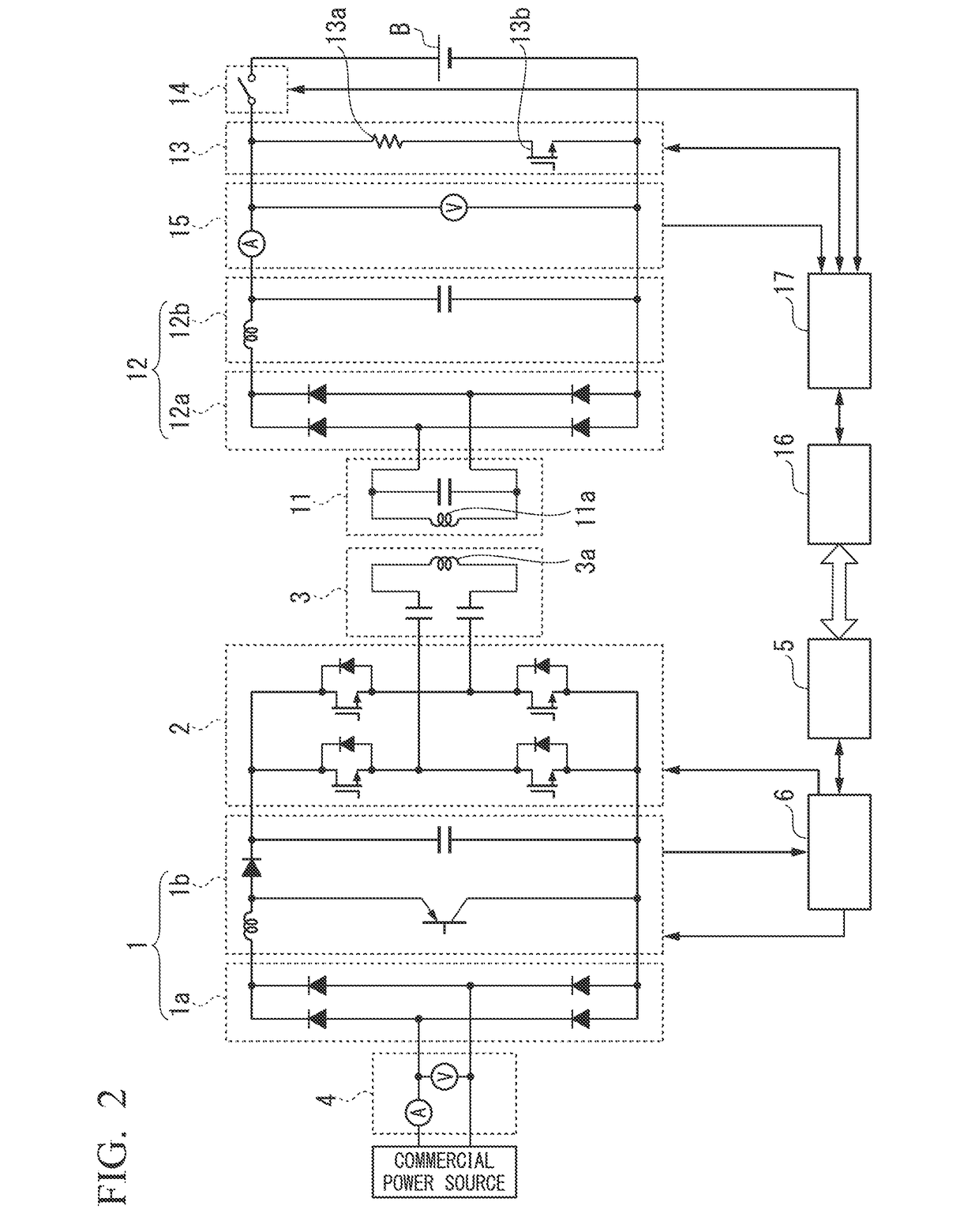
[0020]A power-receiving device R related to the first embodiment constitutes a portion of a wireless power-transmitting system. The wireless power-transmitting system, as shown in FIGS. 1 and 2, is constituted by a power-transmission device S and the power-receiving device R. Additionally, as shown in the drawings, the power-transmission device S is constituted of a power-transmission side power converter 1, an inverter circuit 2, a power-transmission side pad 3, a power-transmission side current / voltage sensor 4, a power-transmission side communicator 5, and a power-transmission side controller 6.

[0021]The power-receiving device R is constituted of a power-receiving side pad 11, a power-receiving side power converter 12, a load circuit 13, a switch 14, a power-receiving side current / voltage sensor 15, a power-receiving side communicator 16, and a power-receiving side controller 17.

[0022]The power-tr...

second embodiment

[0057]Next, a wireless power-transmission system related to this disclosure will be described with reference to FIGS. 4 to 6.

[0058]In addition, in the description of the second embodiment to be described below, description will be made with the same reference numerals given to the same parts as those of the above first embodiment, and duplicate description will be omitted.

[0059]The wireless power-transmitting system related to the second embodiment, as shown in FIGS. 4 and 5, is constituted by the power-transmission device S and the power-receiving device R. Additionally, as shown, the power-transmission device S is constituted of the power-transmission side power converter 1, the inverter circuit 2, the power-transmission side pad 3, the power-transmission side current / voltage sensor 4 (detector), and the power-transmission side controller 6.

[0060]The power-receiving device R is constituted of the power-receiving side pad 11, the power-receiving side power converter 12, the load ci...


PUM


Abstract

A power-receiving device is provided with a load circuit including a load and a switching element that are connected in series between a pair of output terminals of a power-receiving side power converter. The load of the load circuit has such a resistance value that the voltage of elements of a power-receiving side pad or the power-receiving side power converter does not reach a breakdown voltage before a power-transmission device stops power transmission to the power-receiving device after the power-receiving device and the load device are disconnected from each other.

Description

TECHNICAL FIELD[0001]This disclosure relates to a power-receiving device, a wireless power-transmitting system, and a power-transmission device.[0002]This application is a Continuation of International Application No. PCT / JP2015 / 068981, filed on Jul. 1, 2015, claiming priority based on Japanese Patent Application No. 2014-137880, filed on Jul. 3, 2014, and Japanese Patent Application No. 2014-257201, filed on Dec. 19, 2014, the content of which are incorporated herein by reference in their entirety.BACKGROUND ART[0003]Patent Document 1 discloses a wireless power-transmitting system that includes a power-transmitting facility that has a primary self-resonance coil, a power-receiving device, such as a hybrid car, which has a secondary self-resonance coil that receives power from the primary self-resonance coil via an electromagnetic field and charges a battery with the received power, and a control device that controls a high-frequency power source device, thereby controlling transmis...

Claims


Application Information

Patent Timeline
Patent Type & Authority Applications(United States)
IPC IPC(8): H02J50/12H02J50/90H02J7/02
CPCH02J50/12H02J50/90H02J7/025H02H9/04H02J7/0031H02J50/80Y02T10/7072Y02T90/14H02J7/00304B60L53/126Y02T10/70H02J7/00308Y02T90/12
Inventor MURAYAMA, TAKAHIKOTAKATSU, YUJIBANDO, TAKAYOSHIMAEKAWA, YUJIARAKI, JUN
Owner IHI CORP
Why Eureka
Try Eureka