
Radio frequency complex reflection coefficient reader

a technology of complex reflection coefficient and radio frequency, which is applied in the direction of transmitter monitoring, electrical equipment, transmission, etc., can solve the problems of large reflection amount that is not acceptable, and problems such as impedance mismatch can be problematic, so as to improve uplink and downlink capacity, improve battery life, and improve wireless device performance

Active Publication Date: 2017-03-30
QORVO US INC
View PDF9 Cites 5 Cited by
  • Summary
  • Abstract
  • Description
  • Claims
  • Application Information

AI Technical Summary

Benefits of technology

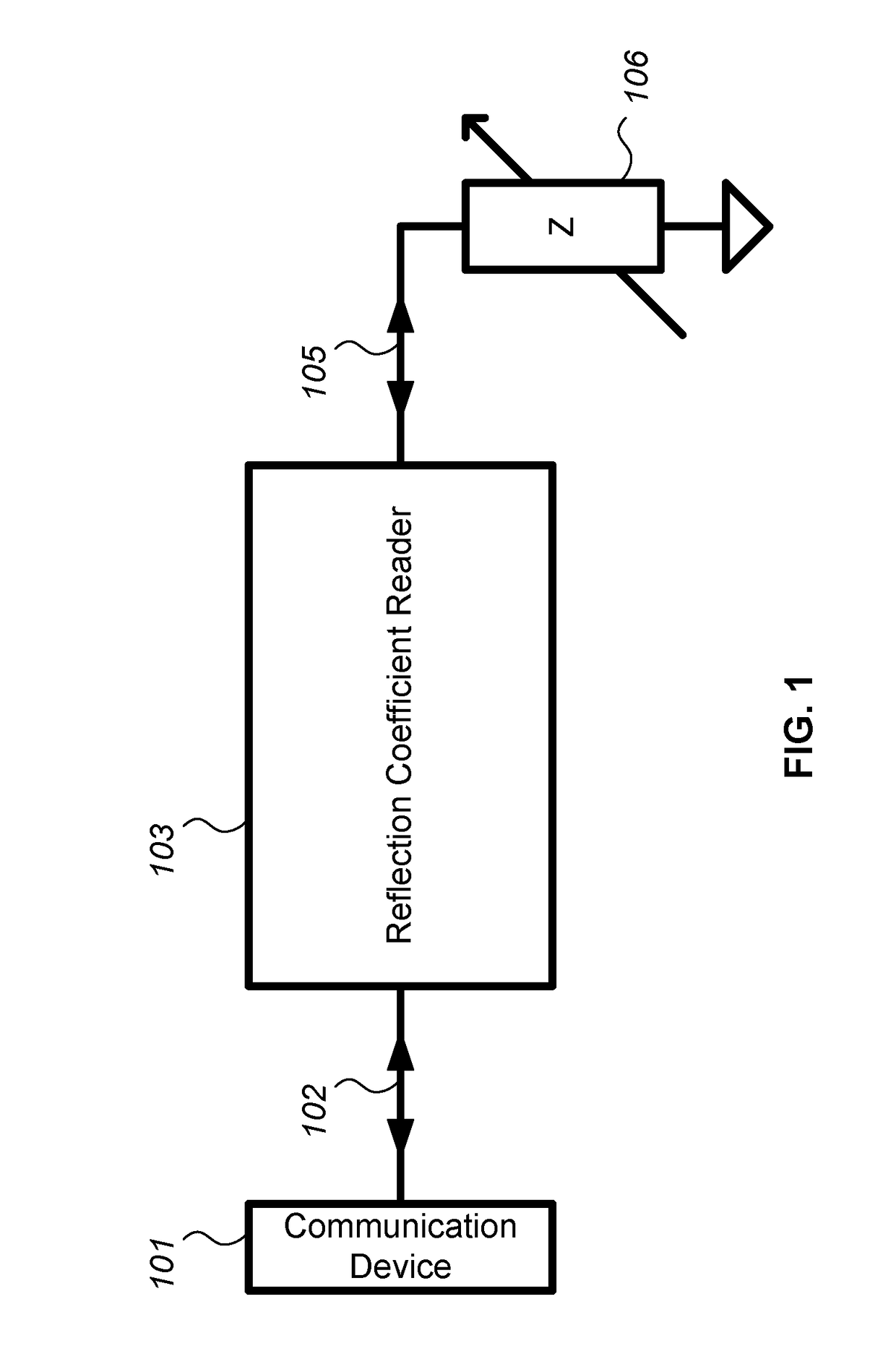
This patent is about a method to determine the performance of a circuit component or whole system by measuring the reflection coefficient, which can help improve wireless devices. The reflection coefficient provides information about the mismatch of impedance, which can be used to correct the performance. The complex value of the reflection coefficient provides more information than just the amplitude. The patent also discusses how to improve the isolation of the transmit signal from the receive signal, which can lead to better performance and battery life. Additionally, the patent mentions the use of antenna tuners to improve the match between the power amplifier and the antenna by measuring and correcting the reflection coefficient. The method can be used for any circuit component or network. Overall, this patent provides technical means to assess and improve the performance of electronic devices.

Problems solved by technology

Sometimes the amount of reflection is so large that it is not acceptable.
Impedance mismatch can be problematic in wireless devices, for example, since the impedance of the antenna changes due to unpredictable environmental factors.

Method used


Image

  • Radio frequency complex reflection coefficient reader
  • Radio frequency complex reflection coefficient reader
  • Radio frequency complex reflection coefficient reader

Examples


Embodiment Construction

[0028]As utilized herein the terms “circuit” and “circuitry” refer to physical electronic components (i.e. hardware) and any software and / or firmware (“code”) which may configure the hardware, be executed by the hardware, and / or otherwise be associated with the hardware. As utilized herein, “and / or” means any one or more of the items in the list joined by “and / or”. As an example, “x and / or y” means any element of the three-element set {(x), (y), (x, y)}. As another example, “x, y, and / or z” means any element of the seven-element set {(x), (y), (z), (x, y), (x, z), (y, z), (x, y, z)}. As utilized herein, the term “exemplary” means serving as a non-limiting example, instance, or illustration. As utilized herein, the terms “e.g.” and “for example” set off lists of one or more non-limiting examples, instances, or illustrations.

[0029]The drawings are of illustrative embodiments. They do not illustrate all embodiments. Other embodiments may be used in addition or instead. Details that may...


PUM


Abstract

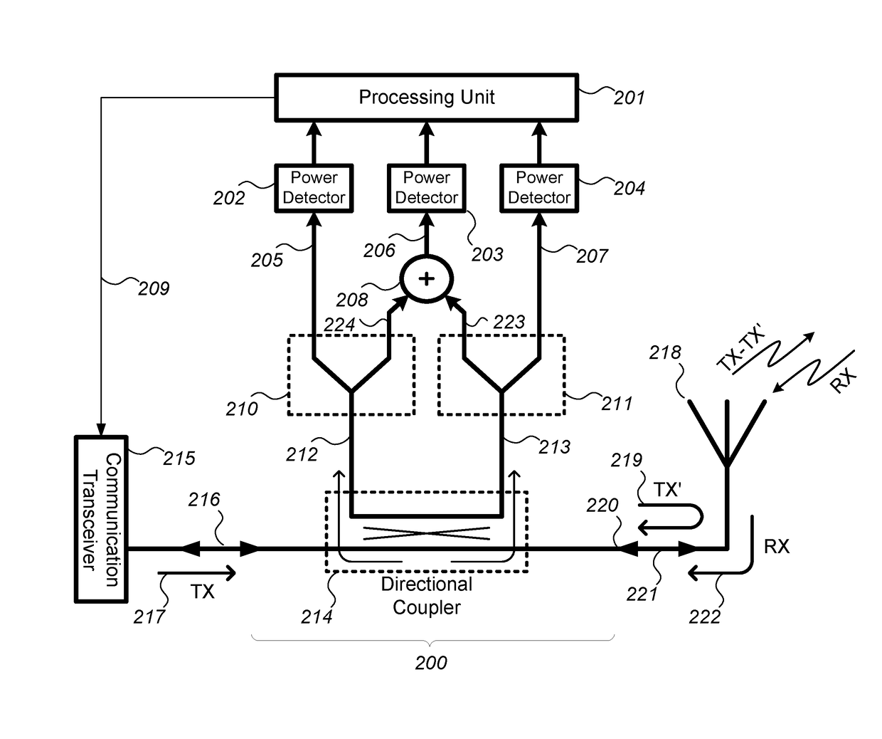
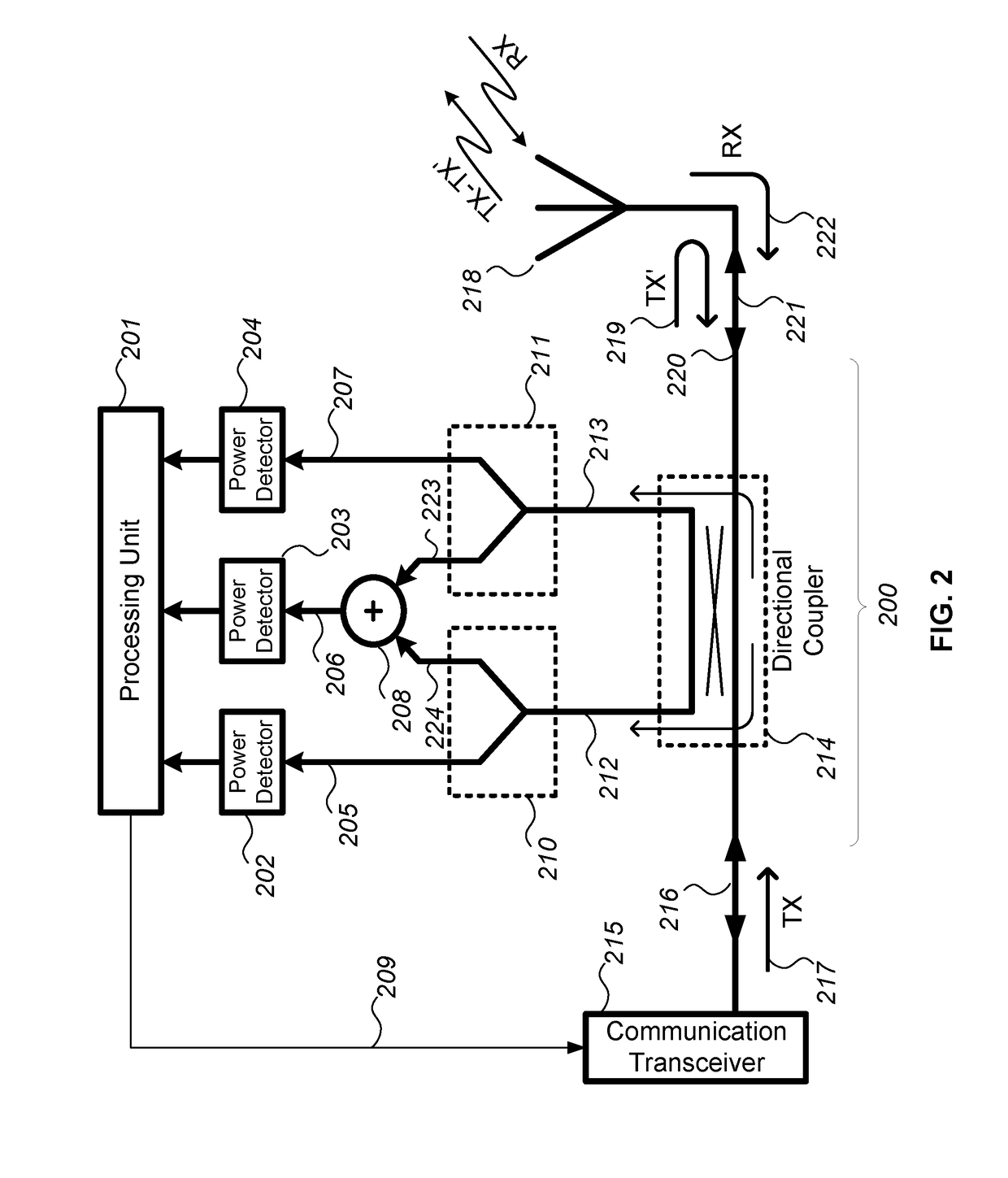
A radio frequency (RF) circuitry includes a device that taps a transmission line and picks up some of electromagnetic signals traveling in both directions. The RF circuitry includes a first detector, a second detector, a third detector, and a processor. The first detector measures a power of a first portion of the tapped electromagnetic signal travelling in one direction. The second detector measures a power of a first portion of the tapped electromagnetic signal travelling in the other direction. The third detector measures a power of a combined signal which includes a second portion of the tapped electromagnetic signal travelling in the one direction and a second portion of the tapped electromagnetic signal travelling in the other direction. The processor determines, based on outputs from the detectors, a relative magnitude and a relative phase of the electromagnetic signals.

Description

CROSS-REFERENCE TO RELATED APPLICATIONS / INCORPORATION BY REFERENCE[0001]This patent application makes reference to, claims priority to, and claims benefit from U.S. Provisional Application No. 62 / 235,020, filed on Sep. 30, 2015.[0002]The above-identified application is hereby incorporated herein by reference in its entirety.FIELD OF THE DISCLOSURE[0003]Certain embodiments of the disclosure relate to electromagnetic components, integrated circuits, and / or wireless communication devices and systems. More specifically, certain embodiments of the disclosure relate to a method and system that use a radio frequency (RF) complex reflection coefficient reader.BACKGROUND OF THE DISCLOSURE[0004]With the recent explosion of the use of wireless devices, the demand for better performing devices is greater than ever. Cell phones, tablets, or any other wireless devices can perform better by providing more computational power, higher downlink and uplink capacity, and more sensor capabilities, all w...

Claims


Application Information

Patent Timeline
Patent Type & Authority Applications(United States)
IPC IPC(8): H04B1/00H04B1/48H04B17/10
CPCH04B1/005H04B1/48H04B17/10H04B1/0458
Inventor MANDEGARAN, SAMHASHEMI, HOSSEIN
Owner QORVO US INC
Learn More