Spinal catheter having multiple obstruction-clearing features

a technology of a spinal catheter and a feature, applied in the field of spinal catheters, can solve the problems of increasing the risk of injuring the spinal cord of the patient, difficult accurate placement of known contacts,

Inactive Publication Date: 2017-04-06
PYLES STEPHEN
View PDF0 Cites 0 Cited by
  • Summary
  • Abstract
  • Description
  • Claims
  • Application Information

AI Technical Summary

Problems solved by technology

However, accurately placing known contacts can be rather difficult because the epidural space that surrounds the spinal cord typically contains fat, veins, adhesions, and connective tissue membranes which interfere with, and often prevent, the accurate placement of the contacts.
All of this insertion, removal, insertion, removal, insertion, removal, and reinsertion presents increased risks of injuring the spinal cord of the patient.

Method used


Image

  • Spinal catheter having multiple obstruction-clearing features
  • Spinal catheter having multiple obstruction-clearing features
  • Spinal catheter having multiple obstruction-clearing features

Examples


second embodiment

[0060]Next, the practitioner advances the stimulator lead 410 (as indicated by the directional arrow) further into epidural space 6 until the insertion section 419a of the distal-end portion 419 of the stimulator lead 410, or at least the balloon 424 mounted to it (or extending axially from it, as in the second embodiment), are positioned within the pilot opening 7a (FIG. 12). Then, the practitioner directs delivery of the second fluid 431 from the second fluid source through the second lumen 430 to expand and contract the balloon 424 for further displacement of the tissue obstruction 8. For example, the practitioner can operate controls (e.g., valving) of the second fluid source (not shown) to control pressurized flow of the second fluid 431 through the second lumen and out of the second outlet with sufficient pressure to inflate the balloon radially outward relative to the distal-end portion of the stimulator-lead shaft until the pilot opening is expanded (FIGS. 13-14). Once the p...

fourth embodiment

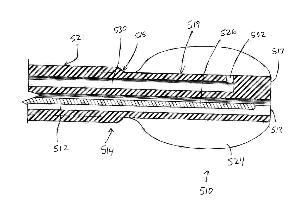
[0067]In this embodiment, however, there are no electrical-stimulation contacts for delivering therapeutic energy. As such, the contact portion of the spinal cord stimulator lead 310 of the fourth embodiment is in this embodiment referred to simply as the main extension or elongation portion 521, as it has no contacts on it.

[0068]The distal-end portion 519 of the shaft 514 has a smaller diameter than the main portion 521 of the shaft and as such defines a leading insertion section of the shaft. This enables the distal-end portion 519 (and the distensible balloon 524 mounted onto it) to fit into small-diameter partial / pilot openings pressure-ablated in the tissue obstructions by the first pressurized fluid (or naturally occurring without the need for the first-fluid pressure-ablation). Typically the shaft 514 includes a transition portion 515 that is tapered (e.g., smoothly radially increasing in the proximal direction, as depicted) between the smaller-diameter distal-end portion 519...


PUM

PropertyMeasurementUnit
volumeaaaaaaaaaa
sizeaaaaaaaaaa
angleaaaaaaaaaa

Abstract

A spinal catheter for insertion into the epidural space of a human or animal subject includes first and second lumens. A pressurized fluid can be discharged through the first lumen directly onto a tissue obstruction to form a partial / pilot or full / final opening in the tissue obstruction. If a full opening was not formed sufficient for passage of the stimulator lead, the distal-end portion of the stimulator lead can be inserted into the partial opening and then a pressurized fluid can be delivered through the second lumen and into a distensible balloon for expanding the balloon to clear the tissue obstruction sufficient for passage of the stimulator lead. In this way the catheter can be advanced past a tissue obstruction and into place for use within the epidural space, without having to remove and reinsert multiple surgical implements.

Description

CROSS-REFERENCE TO RELATED APPLICATIONS[0001]This application is a continuation-in-part of U.S. Non-Provisional patent application Ser. No. 14 / 737,735, filed Jun. 12, 2015, which is a continuation-in-part of a divisional U.S. Non-Provisional patent application Ser. No. 14 / 508,035, filed Oct. 7, 2014, which is a divisional of U.S. Non-Provisional patent application Ser. No. 14 / 281,350, filed May 19, 2014, which is a continuation-in-part of U.S. Non-Provisional patent application Ser. No. 13 / 270,501, filed Oct. 11, 2011, which is a divisional of U.S. Non-Provisional patent application Ser. No. 11 / 421,098, filed May 31, 2006, which is a continuation-in-part of U.S. Non-Provisional patent application Ser. No. 11 / 217,061, filed Aug. 31, 2005, which claims priority to U.S. Provisional Patent Application Ser. No. 60 / 606,172, filed Aug. 31, 2004, all of which are hereby incorporated herein by reference in their entireties for all purposes.TECHNICAL FIELD[0002]The present invention relates g...

Claims


Application Information

Patent Timeline
Patent Type & Authority Applications(United States)
IPC IPC(8): A61N1/05A61B6/12A61B17/22A61K38/47A61M27/00A61K9/08A61K47/02A61K31/56A61B17/34A61M25/10
CPCA61N1/0551A61M2025/105A61B6/12A61B17/22A61M25/10181A61M27/00A61K9/08A61K47/02A61K31/56A61K38/47C12Y302/00A61B2017/22062A61B2017/00893A61B2017/22065A61B17/3468A61B17/32037A61B17/3401A61B2017/22039A61B2217/007A61M25/0043A61M25/0054A61M25/0102A61M25/10A61M29/02A61M2025/0007A61M2025/0059A61B17/22032A61B2017/22034
Inventor PYLES, STEPHEN T.GRAUBERT, DANIEL A.
Owner PYLES STEPHEN
Why Eureka
Try Eureka