Method for determining a spatial distribution of the permeability of an electrode of an electrochemical cell

Active Publication Date: 2017-04-06
COMMISSARIAT A LENERGIE ATOMIQUE ET AUX ENERGIES ALTERNATIVES
View PDF0 Cites 0 Cited by
  • Summary
  • Abstract
  • Description
  • Claims
  • Application Information

AI Technical Summary

Benefits of technology

The invention aims to improve the performance of electrochemical cells by providing a method for determining the spatial distribution of a parameter that indicates the permeability of the cell electrodes. This method prevents the formation of new hot points or non-uniform temperatures during operation, which could otherwise reduce the lifetime of the cell. The determined parameter helps to achieve a more uniform temperature distribution in the electrochemical cell.

Problems solved by technology

Specifically, spatial nonuniformities in current density lead to spatial nonuniformities in the temperature of the cell, which may lead, on the one hand, to an increase in the rate of the degradation reactions of the various components of the cell, and on the other hand, to the generation of mechanical stresses of thermal origin that are liable to decrease the mechanical strength of the components of the cell.

Method used


Image

  • Method for determining a spatial distribution of the  permeability of an electrode of an electrochemical cell
  • Method for determining a spatial distribution of the  permeability of an electrode of an electrochemical cell
  • Method for determining a spatial distribution of the  permeability of an electrode of an electrochemical cell

Examples


first embodiment

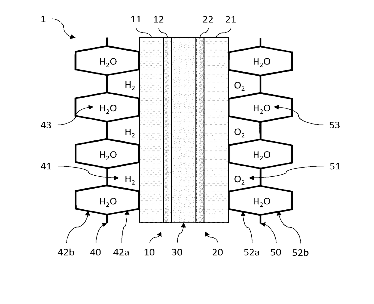
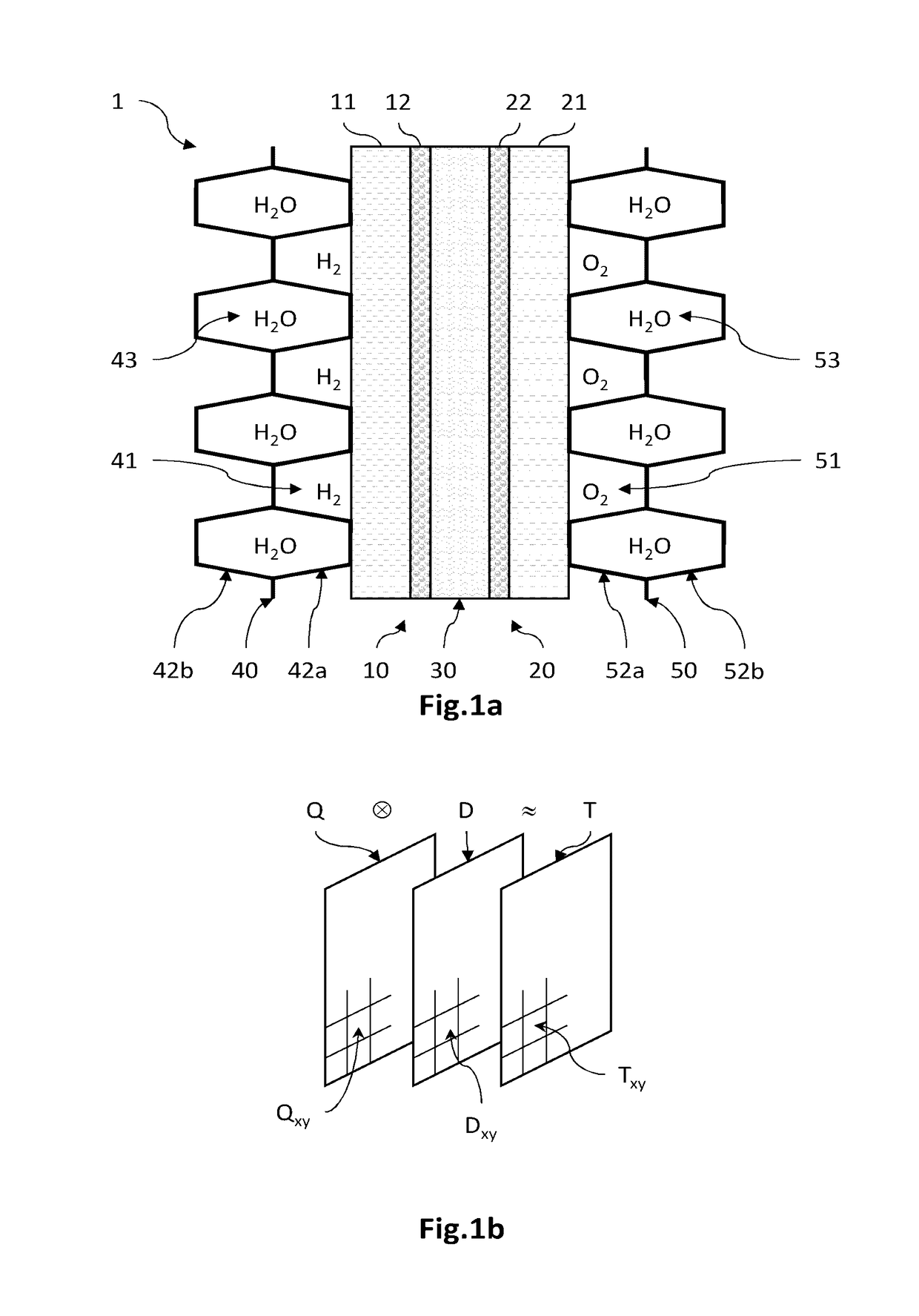
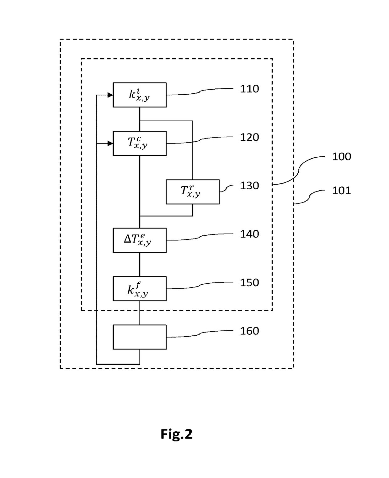
[0077]FIG. 2 is a flowchart of a method for determining the spatial distribution of the parameter of interest representative of the permeability of an electrode, according to a In this example, the parameter of interest is the permeability k of a diffusion layer of an electrode of the cell, for example the cathodic diffusion layer, the value kx,y of which has a direct influence on the local electrical current density Ix,y exchanged locally during the electrochemical reaction and therefore on the local produced heat flux Qx,y.

[0078]Generally, according to this first embodiment, an optimized spatial distribution kx,yf of the permeability k is determined from an estimation of the spatial distribution ΔTx,ye of a difference ΔTe between an effective temperature Tr of the cell in operation—in which cell the permeability is spatially distributed with a given initial distribution—and a preset set-point temperature Tc. It is then possible to modify the permeability k of the diffusion layer ...

second embodiment

[0088]FIG. 3 is a flowchart of a method for determining the spatial distribution of a parameter of interest representative of the permeability of a diffusion layer of at least one electrode of an electrochemical cell, according to a In this example, the parameter of interest is the permeability k of the diffusion layer, here the cathode, the value of which has a direct influence on the electrical current density produced locally during the electrochemical reaction.

[0089]Generally, according to this second embodiment, the spatial distribution kx,yf of the permeability k is determined from the estimation of the spatial distribution of the production of heat necessary to obtain the spatial distribution of a set-point temperature, while taking into account the spatial distribution of a thermal quantity representative of the effective heat removal in the cell. It is then possible to modify the initial distribution of the permeability of the diffusion layer so that it has an optimized sp...


PUM


Abstract

The invention relates to a method for determining a spatial distribution (kx,yf) of a parameter of interest (k) representative of a permeability of a diffusion layer of at least one electrode of an electrochemical cell, comprising steps in which a spatial distribution (kx,yf) of the parameter of interest (k) is determined depending on the spatial distribution (Qx,ye) of a second thermal quantity (Qe) estimated beforehand from the spatial distribution (Tx,yc) of a set-point temperature (Tc) and from the spatial distribution (Dx,yr) of a first thermal quantity (Dr).

Description

TECHNICAL FIELD[0001]The technical field of the invention is that of electrochemical reactors including a stack of electrochemical cells, such as fuel cells and electrolyzers, and more precisely that of methods for determining a parameter representative of the permeability of at least one electrode of the electrochemical cell, and that of methods for producing an electrochemical-cell electrode.STATE OF THE PRIOR ART[0002]An electrochemical reactor such as a fuel cell or electrolyzer conventionally includes a stack of electrochemical cells that each comprise an anode and a cathode that are electrically separated from each other by an electrolyte, an electrochemical reaction taking place in each cell between two reactants that are continuously fed thereto. In the case of a hydrogen fuel cell, the fuel (hydrogen) is brought into contact with the anode, whereas the oxidant (oxygen), which is for example contained in air, is brought into contact with the cathode. The electrochemical reac...

Claims


Application Information

Patent Timeline
IPC IPC(8): H01M8/0297C25B9/06C25B15/02H01M8/0202C25B9/17
CPCH01M8/0297C25B15/02C25B9/063H01M8/0202H01M4/861H01M8/04305H01M8/04365H01M8/04731H01M2008/1095Y02E60/36Y02P70/50Y02E60/50C25B11/036
Inventor ROBIN, CHRISTOPHEVINCENT, REMIGERARD, MATHIASJABBOUR, LARA
Owner COMMISSARIAT A LENERGIE ATOMIQUE ET AUX ENERGIES ALTERNATIVES
Why Eureka
Try Eureka