

Belt cooling system
- Summary
- Abstract
- Description
- Claims
- Application Information
AI Technical Summary
Benefits of technology
Problems solved by technology
Method used
Image

Examples
Embodiment Construction
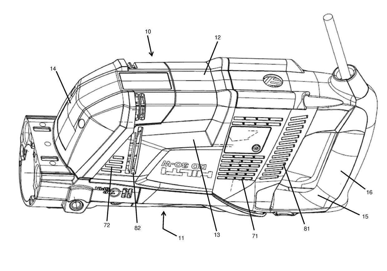
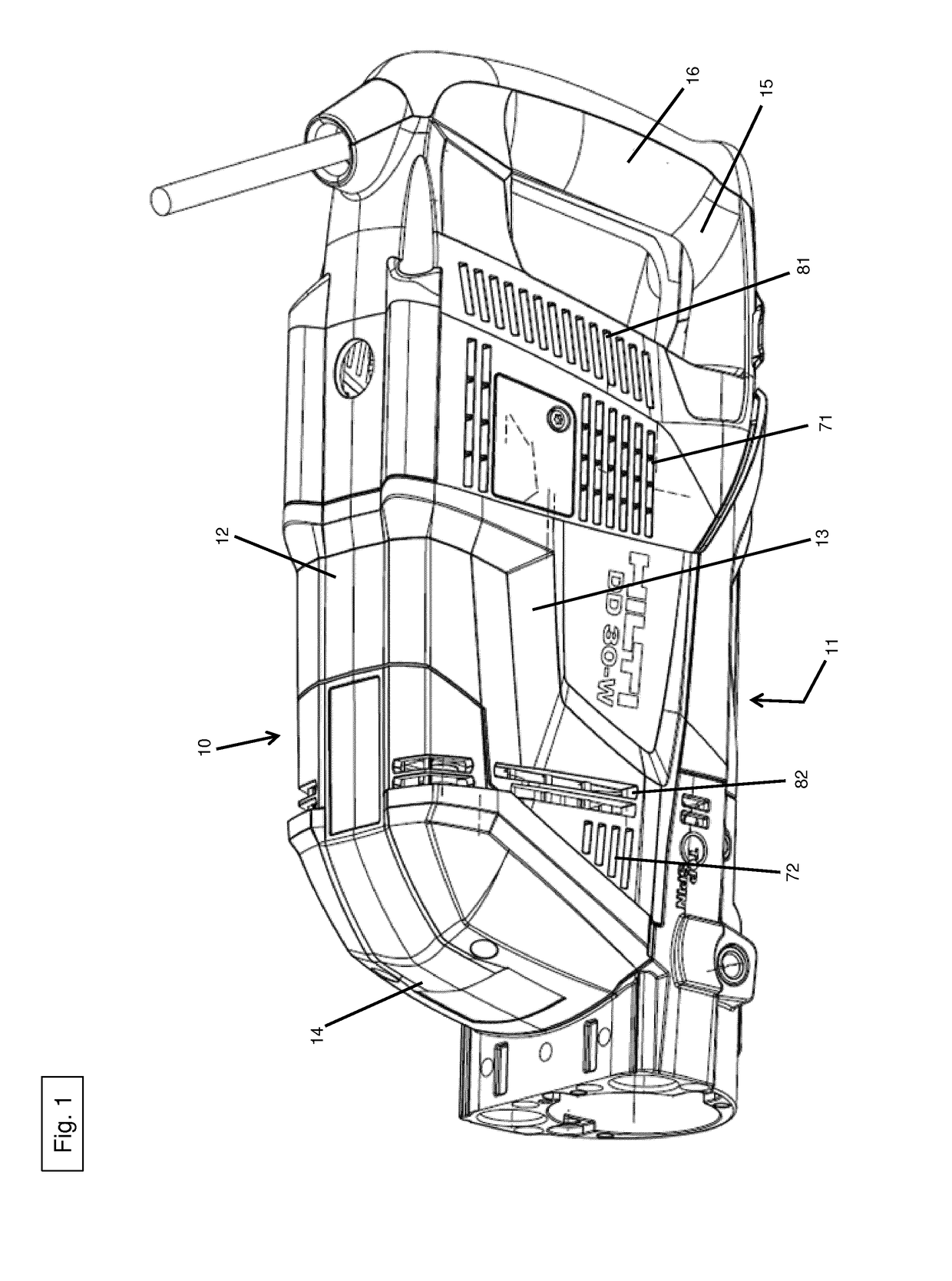
[0019]FIG. 1 shows a power tool 1 according to a first embodiment. The power tool 1 is a core drill with a belt drive 50.
[0020]The power tool 1 configured as a core drill comprises a housing 10, an electric motor 20, a drive shaft 22, a first fan 30, a second fan 40, and a belt drive 50.
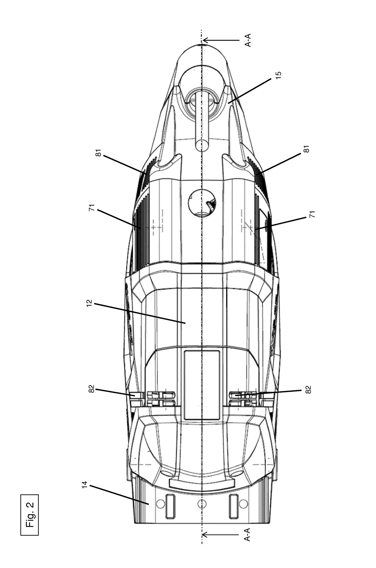
[0021]The housing 10 comprises a top 11, a bottom 12, a right-hand side 13, a left-hand side (not shown here), a front end 14 and a rear end 15. FIG. 1 shows the bottom 12, the front end 14 and the right-hand side 13 of the housing 10. FIG. 2 especially shows the bottom 12 of the housing 10. A tool in the form of a core bit (not shown here) can be positioned on the front end 14. There is a handle 16 on the rear end 15 that allows a user (not shown here) to hold or guide the core drill 1. The right-hand side 13 shown in FIG. 1 is essentially identical to the left-hand side (not shown here).
[0022]As is shown in FIG. 3, the electric motor 20 is positioned in the housing 10 and transmits a torque generat...
PUM
| Property | Measurement | Unit |
|---|---|---|
| Force | aaaaa | aaaaa |
| Pressure | aaaaa | aaaaa |
Abstract
Description
Claims
Application Information