Electric machine with improved heat management

a technology of heat management and electric machines, applied in the direction of dynamo-electric machines, synchronous motors, supports/encloses/casings, etc., can solve the problems of overproportionality, high temperature, high thermal load, etc., and achieve the reduction of heat conducted via electrical contacts from the stator to the control electronics, the effect of significantly reducing the thermal load of the control electronics integrated in the electric machin

Active Publication Date: 2013-10-17
ROBERT BOSCH GMBH
View PDF9 Cites 4 Cited by
  • Summary
  • Abstract
  • Description
  • Claims
  • Application Information

AI Technical Summary

Benefits of technology

[0003]The electric machine according to the invention has the advantage over the prior art that thermal loading of the control electronics integrated in the electric machine can be significantly reduced. In particular, by means of the concept according to the invention, the radiation heat from the stator onto the control electronics can be reduced and the heat conducted via electrical contacts from the stator to the control electronics can also be reduced. This is achieved according to the inventi

Problems solved by technology

In this case, the rotor is arranged in the wet region and the stator is arranged in the dry region, wherein generally only internal rotor motors are implemented since the splash losses in the wet region are otherwise overproportionally great in the case of large rotor diameters.
Owing to the integration of th

Method used


Image

  • Electric machine with improved heat management
  • Electric machine with improved heat management

Examples


Embodiment Construction

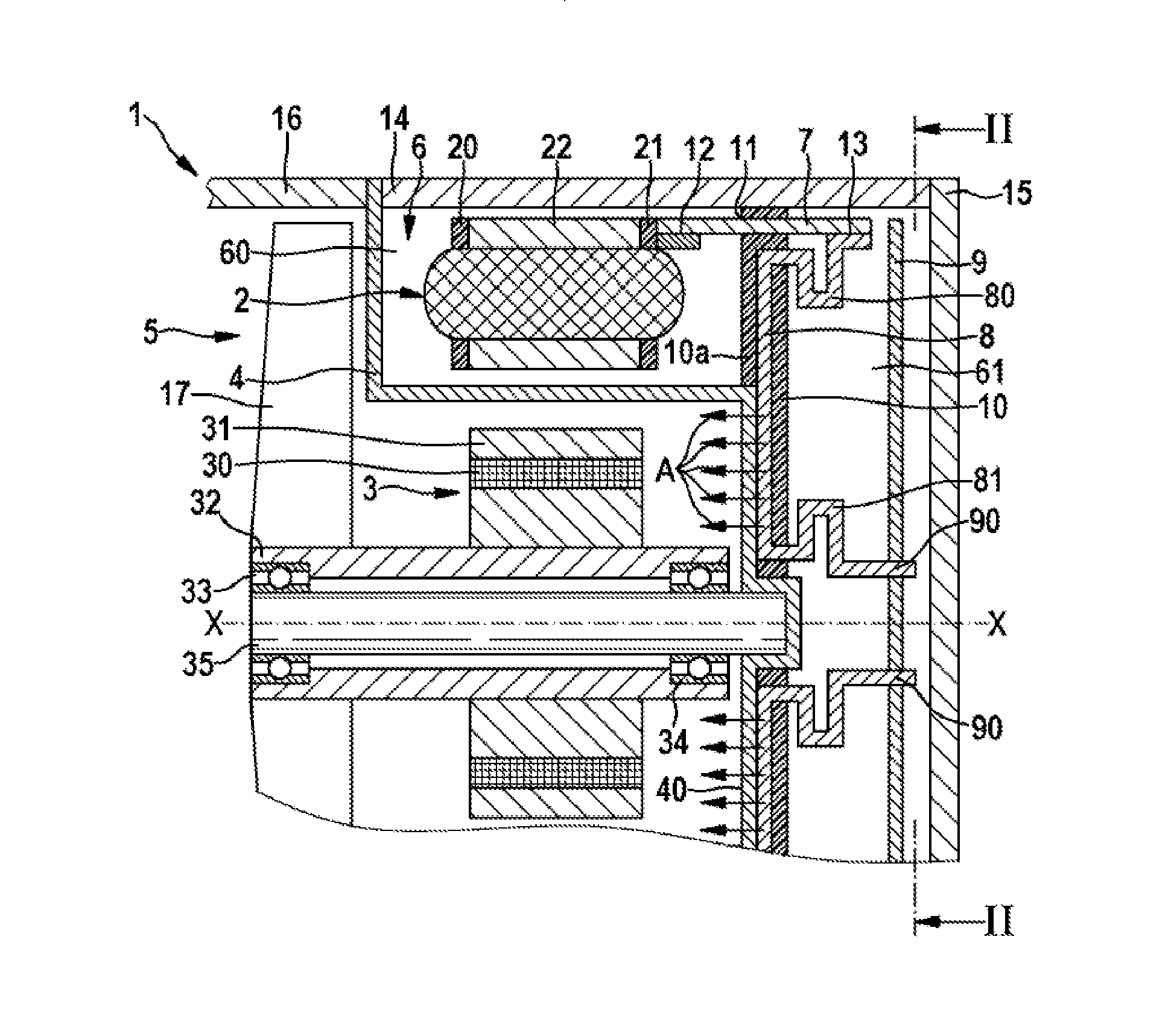
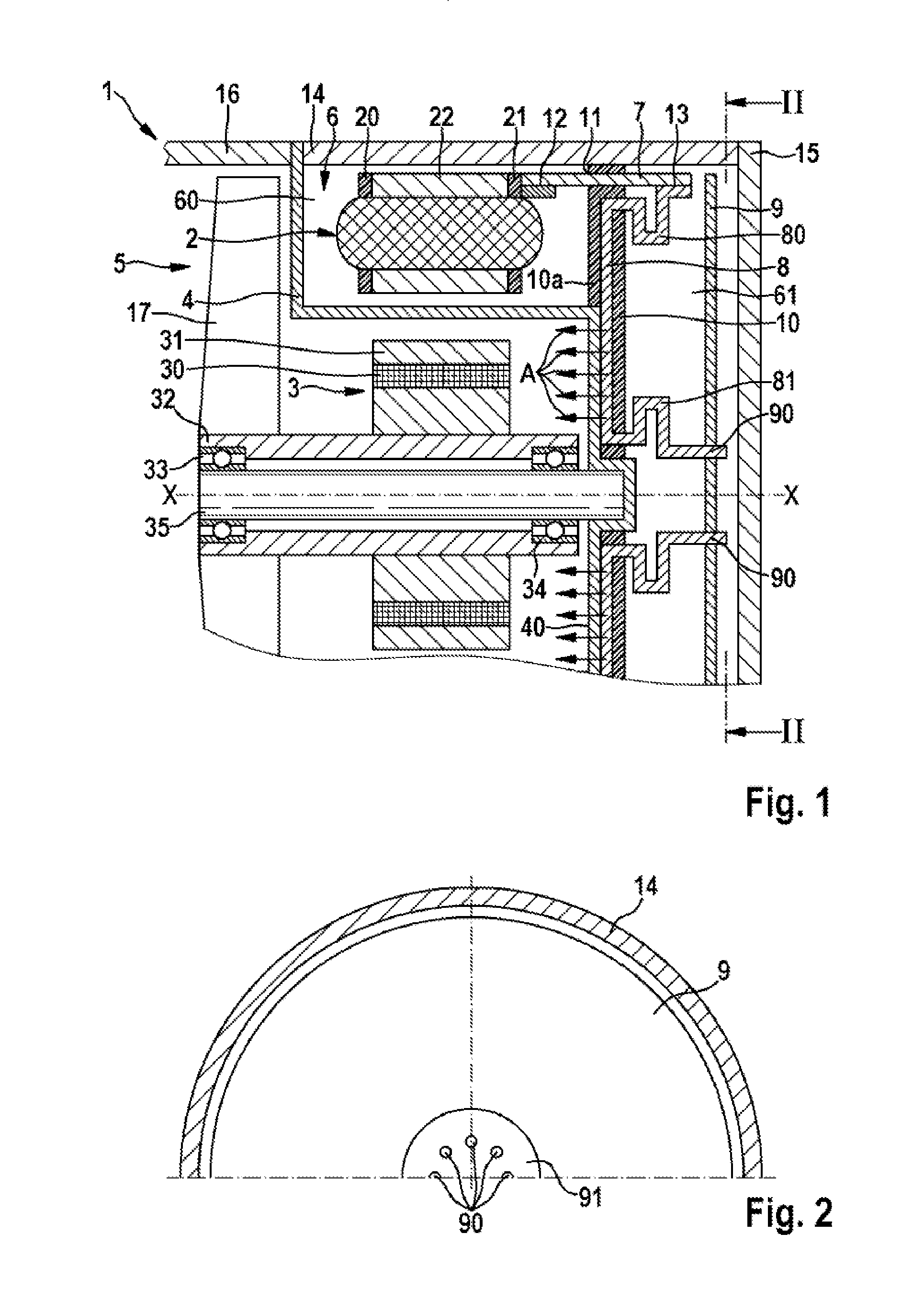
[0014]An electric machine 1 in accordance with an exemplary embodiment of the invention will be described in detail below with reference to FIGS. 1 and 2.

[0015]In this case, the electric machine 1 comprises a stator 2 and a rotor 3, wherein a split cage 4 is arranged between the stator and the rotor. The split cage 4 divides the electric machine into a wet region 5 and a dry region 6. The split cage 4 is in this case fixed on the housing, wherein the housing comprises a motor housing 14, a cover 15 and a pump housing 16. The rotor 3 is fastened on a rotor shaft 32 and comprises permanent magnets 30 and a magnetic return path 31. The rotor shaft 32 is in the form of a hollow shaft and is mounted on a locationally fixed spindle 35 via two bearings 33, 34. In this case, the spindle 35 is fixedly fixed on the split cage 4 in a correspondingly formed cutout in the base 40 of the split cage.

[0016]The stator 2 comprises a laminate stack, a winding and a first and a second insulating mask 2...


PUM


Abstract

The invention relates to an electric machine, comprising a stator (2), a rotor (3), a split cage (4), which separates a wet region (5) from a dry region (6), control electronics (9) and an interconnection element (7, 8), which produces an electrical contact between the stator (2) and the control electronics (9), wherein the rotor (3) is arranged in the wet region (5), wherein the interconnection element (7, 8) is surrounded at least partially by an insulating element (10), and wherein the insulating element (10) divides the dry region (6) into a first subregion (60), in which the stator (2) is arranged, and a second subregion (61), in which the control electronics (9) are arranged.

Description

BACKGROUND OF THE INVENTION[0001]The present invention relates to an electric machine with improved heat management, wherein the electric machine is a so called wet rotor machine with a split cage, which separates a wet region from a dry region.[0002]Electric machines in the form of EC wet rotor motors are known in various configurations and are generally used for applications in which a rotary movement is produced in the medium and a dynamic sealing is avoided. One use sector is pumps, for example. In order to achieve physical forms which are as small as possible, control electronics, for example in the form of a printed circuit board, are integrated in a dry region of the electric machine. In this case, the rotor is arranged in the wet region and the stator is arranged in the dry region, wherein generally only internal rotor motors are implemented since the splash losses in the wet region are otherwise overproportionally great in the case of large rotor diameters. Owing to the int...

Claims


Application Information

Patent Timeline
IPC IPC(8): H02K19/02
CPCH02K19/02H02K5/128H02K5/225H02K11/33
Inventor RIEHL, GUENTHERBRAUN, JOHANNSCHMID, JOERGHEIER, CHRISTOPHHEID, THOMASMUSCHELKNAUTZ, CLAUDIUSKOENIG, TILOTHIERY, JEROME
Owner ROBERT BOSCH GMBH
Why Eureka
Try Eureka