Spark plug having a thermosensor

a thermosensor and spark plug technology, applied in the field of spark plugs, can solve the problems of inability to accurately measure the temperature conditions directly in the combustion chamber, and the change in temperature in the center electrode may be detected only slowly, so as to improve the control or and the in-engine control and regulation of the internal combustion engine excellent

Inactive Publication Date: 2012-08-14
ROBERT BOSCH GMBH
View PDF8 Cites 2 Cited by
  • Summary
  • Abstract
  • Description
  • Claims
  • Application Information

AI Technical Summary

Benefits of technology

[0003]The spark plug according to the present invention has the advantage over the related art that it allows a cycle-based detection of parameters in the combustion chamber of the internal combustion engine. Nevertheless, the spark plug according to the present invention has a very compact and inexpensive design. This is achieved according to the present invention by the fact that the spark plug has a thermosensor, which is situated on a combustion chamber-side end of the spark plug, for detecting a temperature. One end area of the thermosensor is situated on the spark plug so that it is exposed. The exposed end area of the thermosensor is therefore situated in the combustion chamber in the installed state, so that it is able to record measured data directly from the combustion chamber. The thermosensor is designed in such a way that it is able to detect the temperature values very rapidly, so that a cycle-resolved analysis of processes in the combustion chamber may be performed. Since the thermosensor protrudes into the combustion chamber, it is thus possible, with compact internal combustion engines having a small displacement in particular, to detect parameters directly from the combustion chamber. In particular, unwanted deviations in value acquisition, such as those which occur with sensors situated on a combustion chamber wall, are avoided due to the exposed and protruding position of the thermosensor according to the present invention. Accurate cycle-corrected values may thus be determined according to the present invention and used for control of the internal combustion engine.
[0004]The thermosensor is preferably adjacent to the ground electrode in particular. This makes it possible for the thermosensor to supply an accurate value for a temperature in an ignition cycle. Alternatively, the thermosensor is situated opposite the ground electrode. It is possible in this way for a temperature to be detectable over the combustion sequence.
[0005]Furthermore, the thermosensor of the spark plug is preferably designed in such a way that a layer containing chromium is situated on an end area of the thermosensor and a protective layer is applied to the layer containing chromium. The thermosensor is designed in such a way that a layer containing chromium is used instead of a thermocouple and the two thermolines are connected via the layer containing chromium. The protective layer protects the layer containing chromium during operation of the internal combustion engine. Through this design, it is possible for the thermosensor to be able to record temperatures very rapidly and accurately.
[0011]In particular, the layer containing chromium is preferably designed in such a way that it has a layer thickness between 0.1 μm and 10 μm, in particular 2 μm. Furthermore, the protective layer more preferably has a layer thickness between 0.1 μm and 10 μm and in particular 0.2 μm. According to another preferred embodiment of the present invention, a layer thickness of the layer containing chromium and a layer thickness of the protective layer are the same. In this way an especially compact end area having excellent sensor properties may be made available.
[0013]According to another preferred embodiment of the present invention, the end area of the thermosensor in the axial direction of the spark plug is designed in such a way that the outermost point on the end area protrudes the same distance as or less than the ground electrode from a spark plug base plane. This makes it possible to ensure that the end area of the thermosensor protruding away from the spark plug base plane does not protrude too far into the combustion chamber and does not have any interfering influences on the combustion behavior, the ignition, or the fuel injection behavior, and there is no risk of contact with the piston.
[0014]Furthermore, the present invention preferably relates to an internal combustion engine having a spark plug according to the present invention. In addition to a combustion chamber, the internal combustion engine also has a control unit for controlling the internal combustion engine. According to the present invention, the term “control unit” is understood to refer to a unit capable of executing both control and regulating operations. In particular, the control unit may execute a change in injection, a change in valve opening and closing times, a change in an ignition time, etc. The internal combustion engine according to the present invention is provided in such a way that the control unit is connected to the thermosensor on the spark plug, and the control unit is designed to control the internal combustion engine, based on the values transmitted by the thermosensor. In this way, cycle-specific control of the internal combustion engine may be implemented, because the thermosensor supplies high-resolution signals to the internal combustion engine. Excellent in-engine control and regulation of the internal combustion engine is thus made possible by the rapid thermosensor. No additional installation space for the thermosensor need be provided on the internal combustion engine because the thermosensor is an integral component of the spark plug.

Problems solved by technology

However, the resulting changes in temperature in the center electrode may be detected only slowly.
Accurate measurements of temperature conditions directly in the combustion chamber are impossible.

Method used


Image

  • Spark plug having a thermosensor
  • Spark plug having a thermosensor
  • Spark plug having a thermosensor

Examples


Embodiment Construction

[0019]A spark plug 1 according to a preferred exemplary embodiment of the present invention is described in detail below with reference to FIGS. 1 to 3.

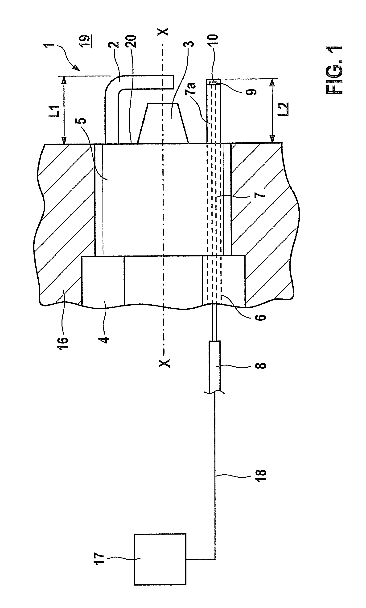
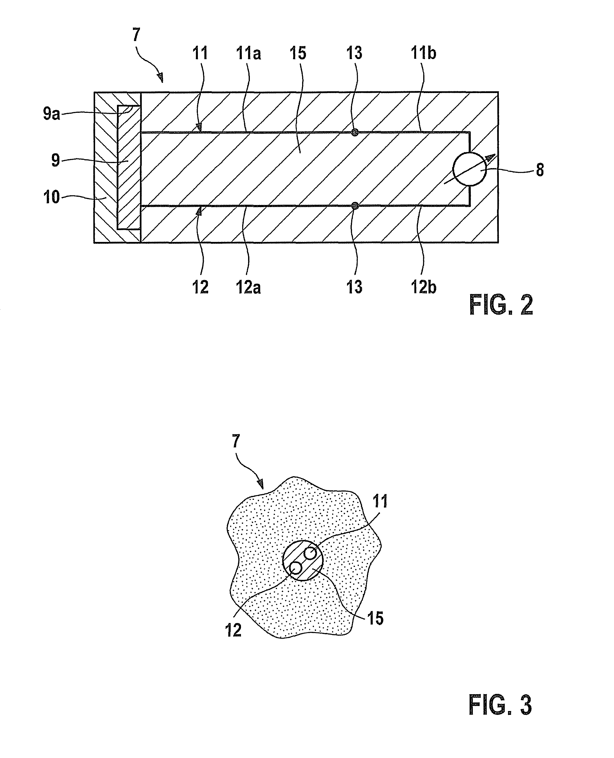
[0020]As FIG. 1 shows, the spark plug is designed in the known manner in general, including a ground electrode 2, a center electrode 3, a shell 4 and a housing 5 provided on the shell for fixation of spark plug 1 in a cylinder head 16. Furthermore, spark plug 1 according to the present invention has a thermosensor 7, which is situated in a borehole 6 in the spark plug. Borehole 6 is formed in shell 4 of the spark plug.

[0021]As FIG. 1 also shows, thermosensor 7 is connected to a control unit 17 by a connecting line 18. Control unit 17 receives signals from the thermosensor and controls or regulates the combustion process in an internal combustion engine. FIG. 1 schematically shows a combustion chamber 19 of the internal combustion engine.

[0022]As FIG. 1 shows, a length L1 of ground electrode 2, starting from a base plane 20 of the spa...


PUM


Abstract

A spark plug includes a ground electrode, a center electrode and a thermosensor for detecting a temperature, the thermosensor being situated on a combustion chamber-side end of the spark plug near the combustion chamber, and an end area of the thermosensor being situated so that it is exposed on the spark plug. In addition, an internal combustion engine having a spark plug is provided.

Description

FIELD OF THE INVENTION[0001]The present invention relates to a spark plug having an integrated thermosensor and an internal combustion engine having such a spark plug.BACKGROUND INFORMATION[0002]Spark plugs for internal combustion engines are known in various embodiments from the related art. German Patent No. DE 40 10 609, for example, describes a spark plug having a temperature sensor and a pressure sensor. The temperature sensor is situated in a borehole in the center electrode, implemented from one side facing away from the combustion chamber. The pressure sensor is situated laterally on the spark plug. The temperature sensor detects a temperature of the center electrode to detect temperature fluctuations in the center electrode. However, the resulting changes in temperature in the center electrode may be detected only slowly. Accurate measurements of temperature conditions directly in the combustion chamber are impossible. However, to allow optimum control of an internal combus...

Claims


Application Information

Patent Timeline
Patent Type & Authority Patents(United States)
IPC IPC(8): H01T13/20H01T13/22
CPCG01K1/14F02D35/024F02D35/025G01K2205/04
Inventor CHRIST, ANSGARHEIDINGER, THORSTEN
Owner ROBERT BOSCH GMBH
Why Eureka
Try Eureka