Onboard electronic control unit

Active Publication Date: 2017-04-13
MITSUBISHI ELECTRIC CORP
View PDF0 Cites 4 Cited by
  • Summary
  • Abstract
  • Description
  • Claims
  • Application Information

AI Technical Summary

Benefits of technology

[0021]As described above, the onboard electronic control unit according to the present invention is configured so that the main control circuit section and the combination control circuit section performing communication of serial signals with each other work together, and that the main control circuit section drive-controls plural electrical loads directly connected to the main control circuit unit or plural electronic loads indirectly connected to the combination control circuit section in accordance with respective operation states of direct input signals and indirect input signals associated with the combination control circuit section,
[0022]the downlink communication data DND transmitted from the main control circuit section to the combination control circuit section includes the first downlink data DND0 with a fixed address and the second downlink data DND1 with a variable address as a pair, which is periodically transmitted in series, the high-speed indirect drive control is performed to the high-speed load by the first downlink data DND0 transmitted every time, and the low-speed indirect drive control is performed to the indirect load of the low-speed response by the second downlink data DND1 in which the transmission target is changed by a designated address even when transmitted every time, at least the low-spe

Problems solved by technology

Therefore, input/output signals indirectly connected from the combination control circuit section to the main control circuit section are l

Method used


Image

  • Onboard electronic control unit
  • Onboard electronic control unit
  • Onboard electronic control unit

Examples


embodiment 1

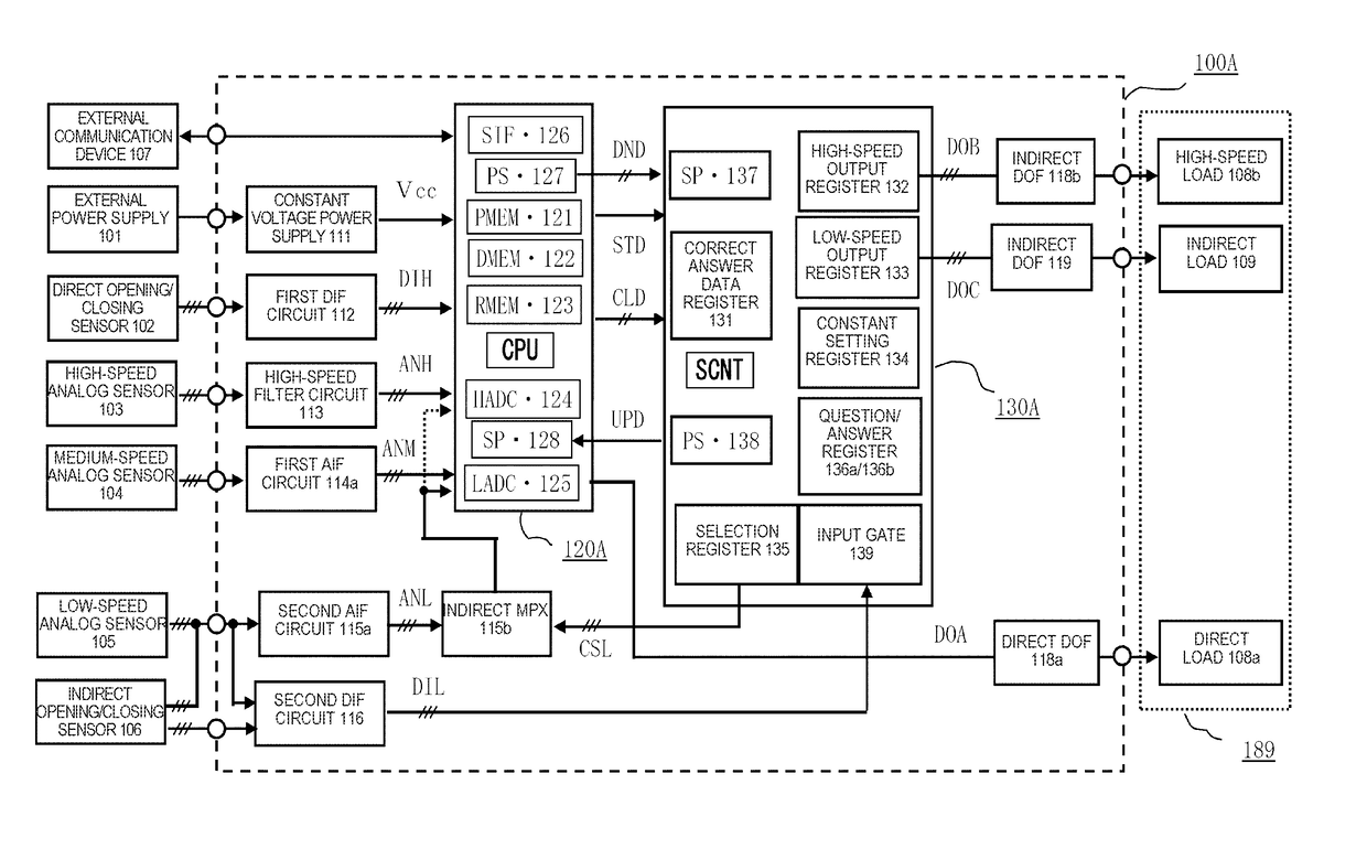
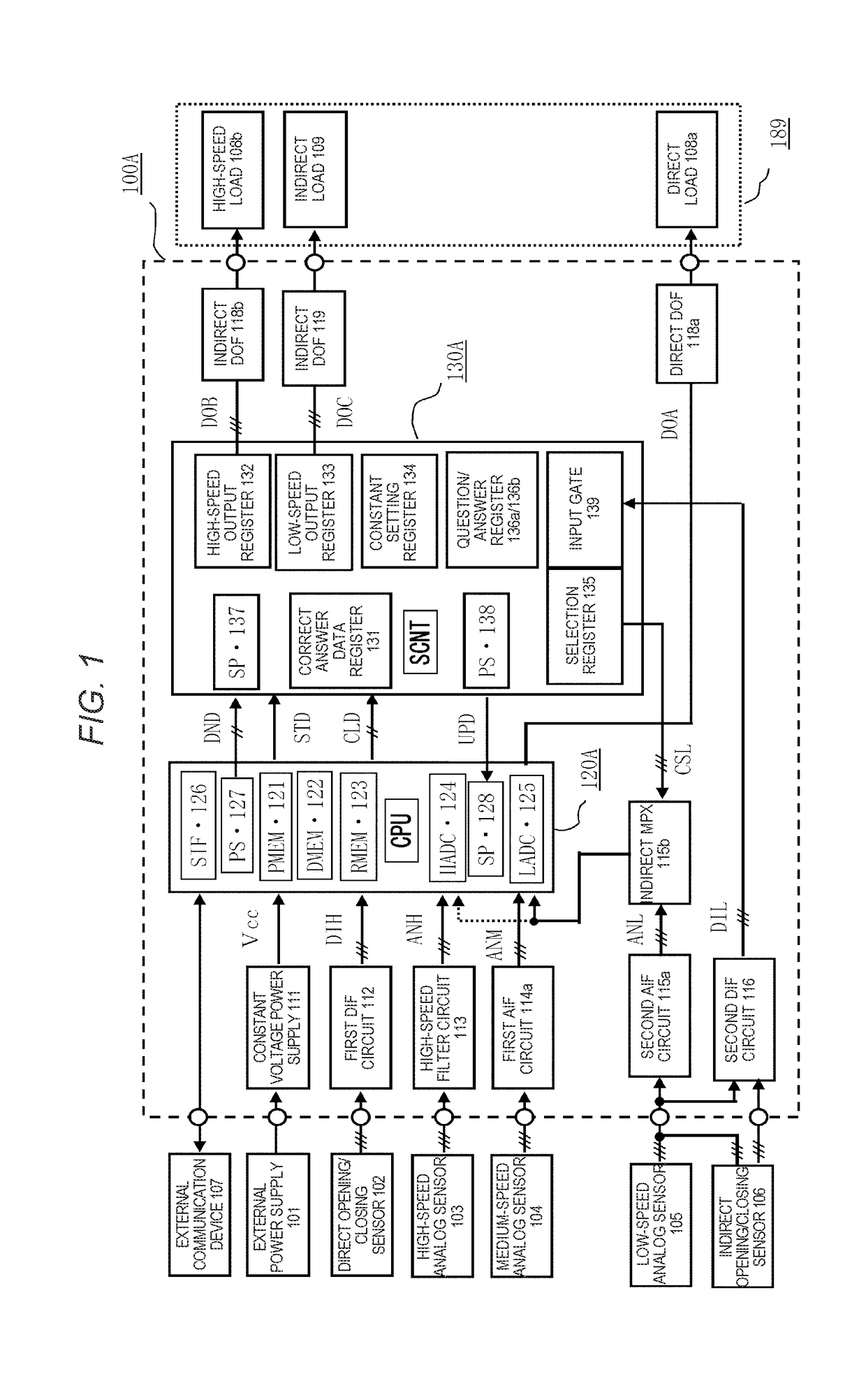
[0041]A configuration in FIG. 1 showing the entire configuration block diagram of an onboard electronic control unit according to Embodiment 1 of the present invention will be explained in detail.

[0042]In FIG. 1, an onboard electronic control unit 100A includes a main control circuit section 120A and a combination control circuit section 130A. The onboard electronic control unit 100A is operated by being connected to an external power supply 101 as an onboard battery through a not-shown power supply switch with a control voltage Vcc fed through an internal constant voltage power supply 111. Plural direct opening / closing sensors 102 which include, for example, a crank angle sensor and a vehicle speed sensor of an engine are inputted in parallel to digital input ports of the main control circuit section 120A as direct input signals DIH through a first digital input interface circuit 112. A high-speed analog sensor 103 which includes, for example, a knock sensor measuring engine sound ...

embodiment 2

[0137]A configuration in FIG. 7 showing the entire configuration block diagram of an onboard electronic control unit according to Embodiment 2 of the present invention will be explained by focusing on different points from that of FIG. 1. In respective drawings, the same symbols denote the same or corresponding sections, and principal different points between FIG. 1 and FIG. 7 are that a main control circuit section 120B is used instead of the main control circuit section 120A, that a combination control circuit section 130B is used instead of the combination control circuit section 130A and that the combination control circuit section 130B is changed from the logic control circuit SCNT to an auxiliary microprocessor SCPU. Moreover, an abnormality data register 134e is added to the combination control circuit section 130B. When abnormality data is stored there, a read request signal REQ is generated with respect to the main control circuit section 120B by a dedicated line.

[0138]In F...

embodiment 3

[0176]A configuration in FIG. 9 showing the entire configuration block diagram of an onboard electronic control unit according to Embodiment 3 of the present invention will be explained by focusing on different points from that of FIG. 1.

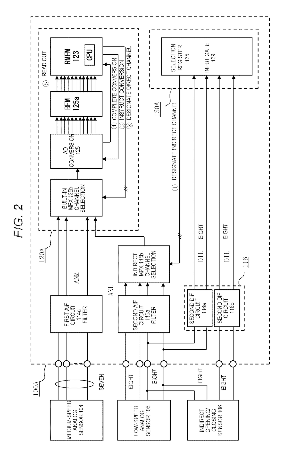
[0177]In respective drawings, the same symbols denote the same or corresponding sections, and principal different points between FIG. 1 and FIG. 9 are that a main control circuit section 120C is used instead of the main control circuit section 120A, that a combination control circuit section 130C is used instead of the combination control circuit section 130A and that the main control circuit section 120C includes only the high-speed AD converter 124 and does not have the multi-channel AD converter 125 capable of selecting input channels by the built-in multiplexer 125b (see FIG. 2). Accordingly, the medium-speed analog input signal ANM and the low-speed analog input signal ANL are inputted to a specific input channel of the high-speed AD converter ...


PUM


Abstract

A downlink communication data DND from a main control circuit section to a combination control circuit section is divided into first and second downlink data, high-speed communication using a downlink clock signal and a transmission start instruction signal is performed, a high-speed load which has been directly driven from the main control circuit section is indirectly driven at high speed from the combination control circuit section by the first downlink data, a low-speed analog input signal ANL which has been indirectly inputted to the combination control circuit section is inputted to a specific input channel of a multi-channel converter through an indirect multiplexer, and channel selection is made by the downlink communication data.

Description

TECHNICAL FIELD[0001]The present invention relates to improvement of an onboard electronic control unit which is, for example, an onboard engine control unit in which a first integrated circuit device to be a main control circuit section and a second integrated circuit device to be a combination control circuit section work together by performing serial communication with each other, and particularly relates to an onboard electronic control unit which is small in size and is capable of performing high-speed processing by reducing the number of input / output terminals of the main control circuit section.BACKGROUND ART[0002]The electronic control unit in which the main control circuit section and the combination control circuit section are connected with each other in series and work together is widely used in practice. However, one of functions of the combination control circuit section is to use the minimum number of input / output terminals in the main control circuit section which ar...

Claims


Application Information

Patent Timeline
IPC IPC(8): F02D41/26F02P1/08F02M51/06F02D9/10F02D35/02
CPCF02D41/26F02D9/105F02D35/027F02M51/061F02P1/083F02D35/028
Inventor IWAGAMI, YUKITADA, JUNJIYAMAMOTO, TOMOKI
Owner MITSUBISHI ELECTRIC CORP
Why Eureka
Try Eureka