Demand-based charging of a heat pipe

a technology of demand-based charging and heat pipes, which is applied in the direction of basic electric elements, electrical equipment, lighting and heating apparatus, etc., can solve the problems of less heat pipe efficiency, and less heat pipe efficiency at a lower power level, so as to increase the amount of liquid, increase the performance of heat pipes at higher power levels, and improve efficiency

Active Publication Date: 2017-04-13
IBM CORP
View PDF3 Cites 5 Cited by
  • Summary
  • Abstract
  • Description
  • Claims
  • Application Information

AI Technical Summary

Benefits of technology

[0007]A heat pipe includes a reservoir of liquid that is connected to a horizontal portion of the heat pipe via a capillary connection. The heat pipe includes a temperature sensor in proximity to a heat interface in the horizontal portion and a controller that controls a heater for the reservoir. As power into the heat pipe increases, the controller turns on the heater, causing the temperature of the liquid in the reservoir to rise. Liquid then passes from the reservoir through the capillary connection into the horizontal portion, thereby dynamically increasing the amount of liquid in the heat pipe, which increases performance of the heat pipe at higher power levels. When the reservoir heater is turned off, as the heat pipe cools, the liquid condenses and flows back through the capillary connection into the reservoir. The result is a heat pipe that is more efficient at lower power levels and still maintains high efficiency at higher power levels due to the demand-based charging of the liquid based on power level.

Problems solved by technology

However, at lower heat energy rates, the performance of heat pipes that are overcharged or saturated is less than heat pipes that are charged with less liquid.
This same heat pipe will work less efficiently at a lower power, meaning the temperature of the processor will be higher than if a heat pipe that were less charged with liquid were used.
Because excessively high temperatures can cause a catastrophic failure in a processor, the decision is usually made to overcharge or saturate the heat pipes in a processor heat sink so they can handle maximum processor power.

Method used


Image

  • Demand-based charging of a heat pipe
  • Demand-based charging of a heat pipe
  • Demand-based charging of a heat pipe

Examples


Embodiment Construction

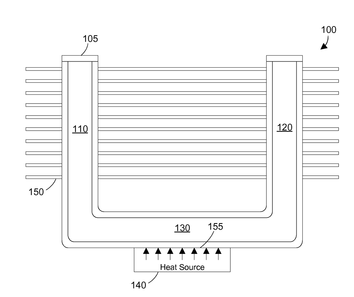
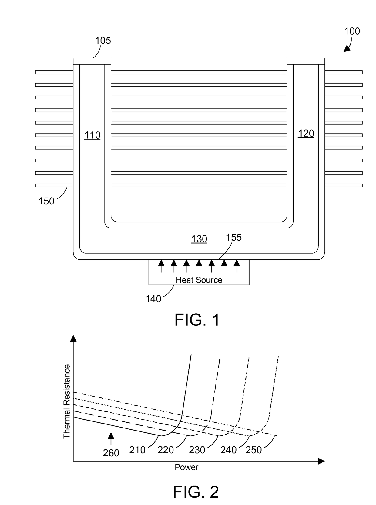
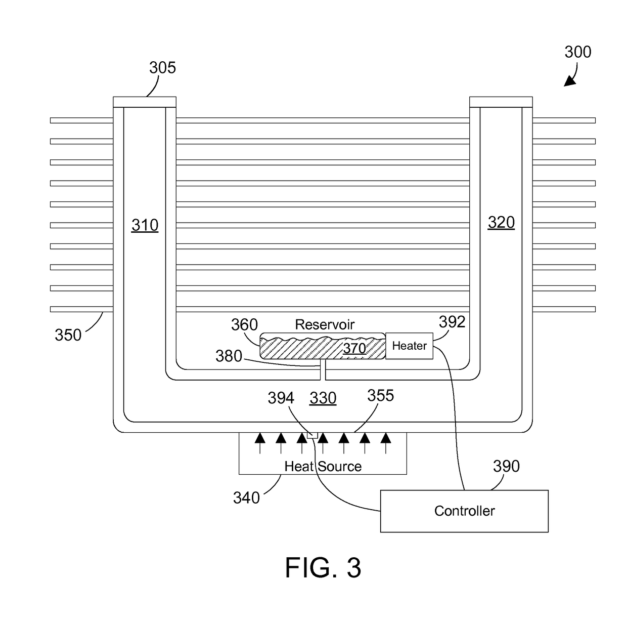
[0016]The disclosure and claims herein relate to a heat pipe that includes a reservoir of liquid that is connected to a horizontal portion of the heat pipe via a capillary connection. The heat pipe includes a temperature sensor in proximity to a heat interface in the horizontal portion and a controller that controls a heater for the reservoir. As power into the heat pipe increases, the controller turns on the heater, causing the temperature of the liquid in the reservoir to rise. Liquid then passes from the reservoir through the capillary connection into the horizontal portion, thereby dynamically increasing the amount of liquid in the heat pipe, which increases performance of the heat pipe at higher power levels. When the reservoir heater is turned off, as the heat pipe cools, the liquid condenses and flows back through the capillary connection into the reservoir. The result is a heat pipe that is more efficient at lower power levels and still maintains high efficiency at higher po...


PUM


Abstract

A heat pipe includes a reservoir of liquid that is connected to a horizontal portion of the heat pipe via a capillary connection. The heat pipe includes a temperature sensor in proximity to a heat interface in the horizontal portion and a controller that controls a heater for the reservoir. As power into the heat pipe increases, the controller turns on the heater, causing the temperature of the liquid in the reservoir to rise. Liquid then passes from the reservoir through the capillary connection into the horizontal portion, thereby dynamically increasing the amount of liquid in the heat pipe, which increases performance of the heat pipe at higher power levels. When the heater is off, as the heat pipe cools, the liquid condenses and flows back through the capillary connection into the reservoir. The result is a heat pipe that provides demand-based charging of the liquid based on power level.

Description

BACKGROUND[0001]1. Technical Field[0002]This disclosure generally relates to heat pipes, and more specifically relates to a heat pipe that includes one or more reservoirs that provide demand-based charging.[0003]2. Background Art[0004]A heat pipe is used to transfer heat between a hot interface and a cold interface. The heat pipe includes a liquid in contact with a thermally conductive solid surface at the hot interface. When the hot interface heats up, the liquid turns into a vapor by absorbing heat from the hot interface. The vapor then travels along the heat pipe to the cold interface and condenses back into liquid, which releases the latent heat. The liquid then returns to the hot interface, and the cycle repeats. Heat pipes are highly effective thermal conductors, with an effective thermal conductivity orders of magnitude larger than for other heat transfer methods, such as a solid metal like copper.[0005]Heat pipes are charged with a liquid. The amount of liquid in the heat pi...

Claims


Application Information

Patent Timeline
Patent Type & Authority Applications(United States)
IPC IPC(8): F28D15/06
CPCF28D15/06F28D15/0283F28D15/046F28D2021/0028F28F21/085H01L23/3672H01L23/427F28D15/0275F28D2015/0216F28F3/02
Inventor ANDERL, WILLIAM J.ELISON, BRET P.MANN, PHILLIP V.SINHA, ARVIND K.
Owner IBM CORP
Why Eureka
Try Eureka