Transition apparatus for an energy storage apparatus, and method for producing an energy storage apparatus

a technology of transition apparatus and energy storage device, which is applied in the direction of batteries, multiple hybrid/edl capacitors, and protecting/adjusting hybrid/edl capacitors, etc., can solve the problems of uneven heating of individual cells, increase in individual cell temperature, and heating of the entire energy storage device, so as to achieve high coolant volumetric flow, cost-effective

Inactive Publication Date: 2017-04-13
MAHLE INT GMBH
View PDF9 Cites 3 Cited by
  • Summary
  • Abstract
  • Description
  • Claims
  • Application Information

AI Technical Summary

Benefits of technology

[0009]The first incompressible layer can fill interspaces produced by the roughness profile, level the unevenness in contact surfaces of the temperature-control plate and / or the end plate, and thereby serve as a tolerance transition layer. Overall, therefore, an enlarged real thermal contact surface can be realized. The heat transfer resistance between the energy store and the temperature-control device can be reduced as a result. This can lead to improved heat transfer between the temperature-control device and the energy store. The first incompressible layer can thereby assure an optimized thermal contact. The first incompressible layer can preferably realize a reliable and unvarying contact by means of the incompressible property. The first incompressible layer is preferably free of bubbles and has no compressible bubbles, as is known for conventional tolerance compensation layers. The first incompressible layer can simultaneously realize a gluing of the components, the temperature-control device or temperature-control plate and energy store or end plate or bottom of the energy store.
[0027]The object of the energy storage device is also achieved by an energy storage device with an energy store and a temperature-control device, whereby a transition apparatus of the invention is disposed between the energy store and the temperature-control device. The transition apparatus can have a first incompressible layer which serves as a tolerance compensation layer. Roughnesses with hills and valleys, which are caused by the technical surfaces of the temperature-control device and / or the cells of the energy store, can be smoothed in this way, so that a largest possible thermal contact surface is formed. The thermal contact surface is incompressible after the curing of the curable substances of the first layer and forms a positive connection between the temperature-control device and energy store. In this case, the inventor has determined that thermosetting plastics, as glass-like polymers, can produce a first incompressible layer with an optimal heat transfer.
[0028]The transition apparatus in this case can also form an arrangement of a plurality of functional layers, which makes it possible to influence selectively the thermal resistance between the temperature-control device and the surface of the energy store. In this way, a maximum temperature difference on a surface of the energy store, for example, a battery cell, can be kept as low as possible over time. As a result, for example, a battery cooling plate with a locally adapted thermal interface, also called LaThIn, can be realized.
[0029]As a result, it is no longer necessary to operate a temperature-control plate, for example, a cooling plate, with a suitably high coolant volumetric flow for the temperature control of an energy store, so that the temperature gradient in the coolant is kept low and the energy store or cells of the energy store can be cooled homogeneously. If the thermal resistance of the arrangement of a plurality of functional layers changes along a flow direction of the coolant, thus the coolant volumetric flow can be kept low, because a temperature gradient in the coolant can be compensated by the changing thermal resistance. By being able to avoid a high volumetric flow, low pressure losses occur in the system, so that the other components in the circuit can be dimensioned smaller. Thus, for example, small, light, and cost-effective pumps can be used in the coolant circuit of the temperature-control device.
[0030]In addition, a complex bracing device, which uniformly braces the energy store with the temperature-control device, can be omitted. As a result, inhomogeneities in the contact pressure, which influence the thermal resistance, can be compensated. The greater the contact pressure, the higher the thermal resistance and the better the energy store is cooled. If, therefore, the thermal resistance of the arrangement changes because of the inhomogeneities in the bracing, the differences in the thermal resistance can be compensated by introducing a plurality of functional layers. As a result, additional, complex elements for the bracing can also be omitted.

Problems solved by technology

In the energy storage device, due to resistances within and outside the cells, rapid charging and discharging can lead to an increase in the temperature in individual cells and thereby to heating of the entire energy storage device.
In this case, uneven heating of the individual cells can also be brought about.
The temperature in the cells should not exceed 50° C., however, because temperatures above 50° C. could damage the cells of the energy store permanently.

Method used


Image

  • Transition apparatus for an energy storage apparatus, and method for producing an energy storage apparatus
  • Transition apparatus for an energy storage apparatus, and method for producing an energy storage apparatus
  • Transition apparatus for an energy storage apparatus, and method for producing an energy storage apparatus

Examples


Embodiment Construction

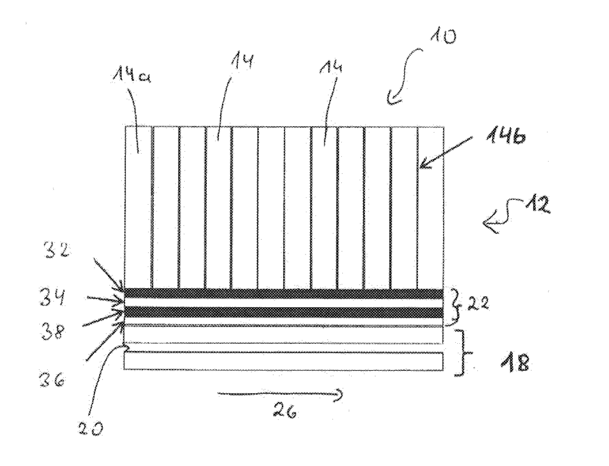
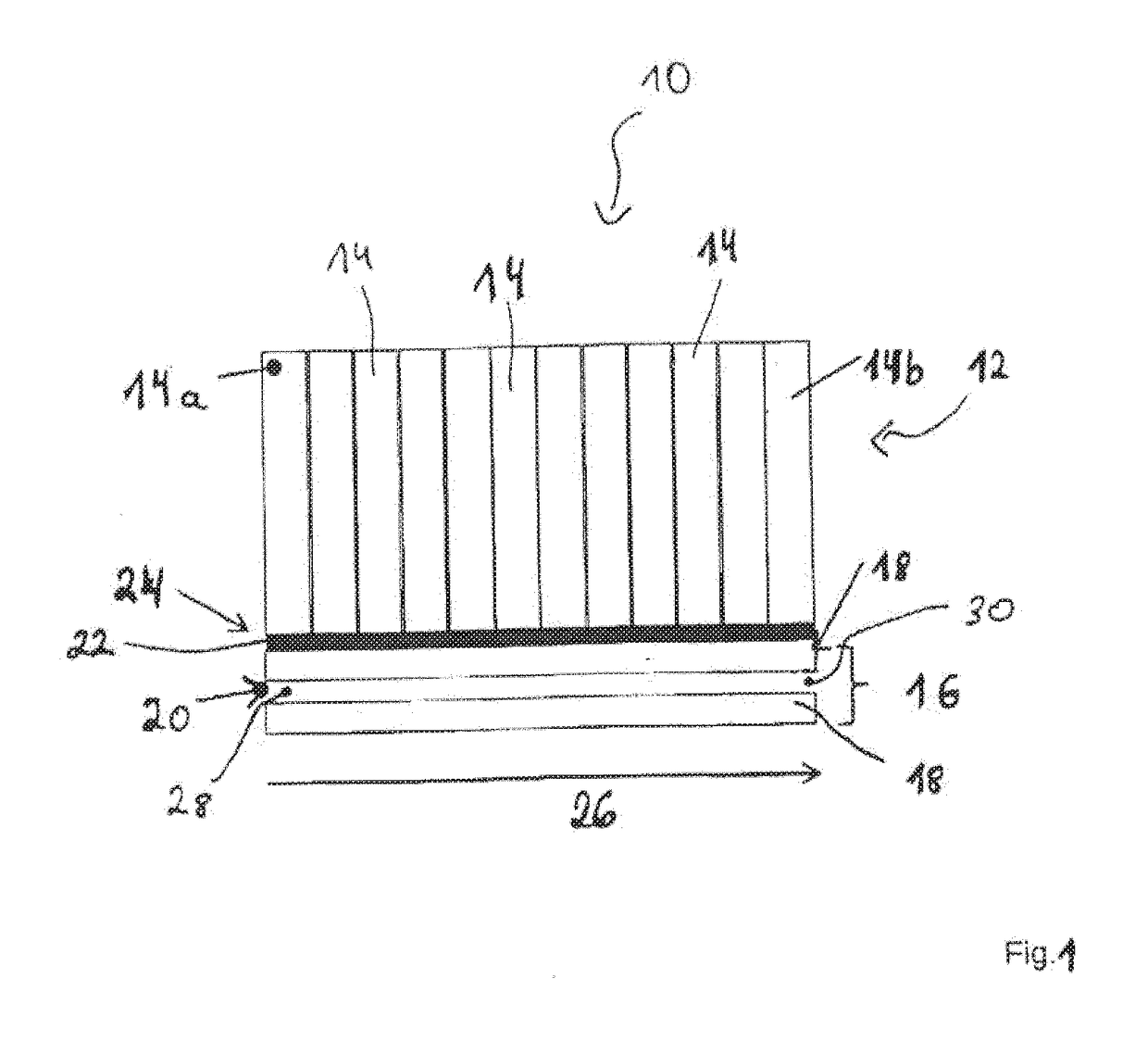
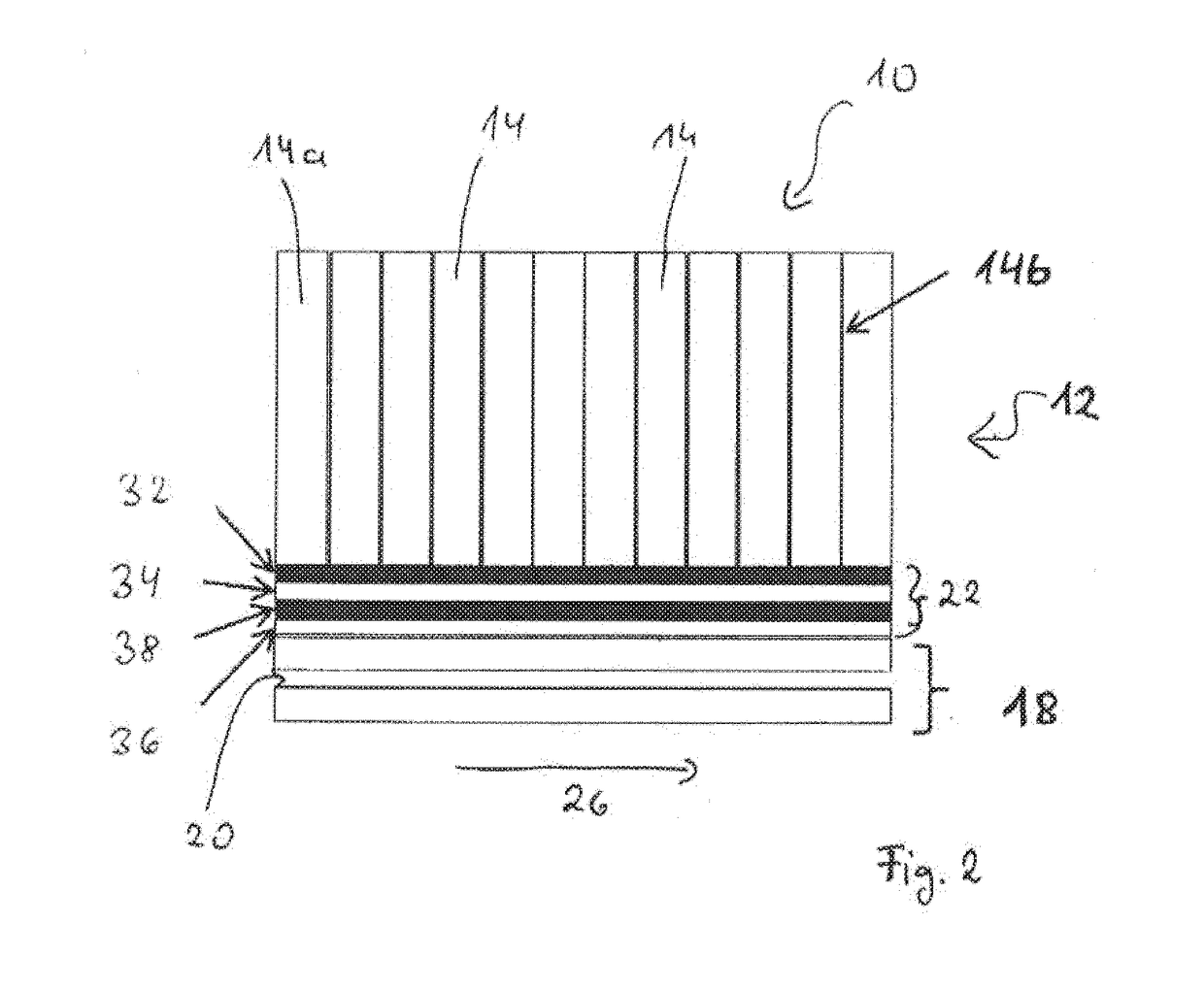
[0044]FIG. 1 in a schematic sectional illustration shows an energy storage device 10 according to an exemplary embodiment of the present invention. Energy storage device 10 has an energy store 12 with cells 14, for example, battery cells 14 or accumulator cells 14, and a temperature-control device 16, which has or forms at least one temperature-control plate. Temperature-control plate 18 is made in particular in the form of a cooling plate 18. Temperature-control plate 18 has at least one flow channel 20 and a thermal transition apparatus 22, arranged between cells 14 and temperature-control plate 18. Cells 14 in this case can be placed on an end plate (not shown here) or a bottom.

[0045]Cells 14 are arranged next to one another on a surface 24 of transition apparatus 22. During operation of energy storage device 10, a fluid can flow through flow channel 20 of temperature-control device or plate 18, in particular cooling plate 18. A flow path length or flow direction of the fluid bet...


PUM

PropertyMeasurementUnit
thicknessaaaaaaaaaa
thicknessaaaaaaaaaa
thicknessaaaaaaaaaa

Abstract

A transition apparatus for an energy storage device which has at least one energy store and one temperature-control device, in particular for a motor vehicle, wherein the transition apparatus is arranged between the energy store and the temperature-control device. The transition apparatus is distinguished in that a first incompressible layer is provided, wherein the first incompressible layer serves as a tolerance compensation layer.

Description

[0001]This nonprovisional application is a continuation of International Application No. PCT / EP2015 / 063029, which was filed on Jun. 11, 2015, and which claims priority to German Patent Application No. 10 2014 212 105.1, which was filed in Germany on Jun. 24, 2014, and which are both herein incorporated by reference.BACKGROUND OF THE INVENTION[0002]Field of the Invention[0003]The invention relates to a transition apparatus for an energy storage device, in particular for a motor vehicle. Furthermore, the invention relates to a method for producing a transition apparatus and an energy storage device.[0004]Description of the Background Art[0005]Energy storage devices with an energy store, which has cells arranged in a stack, are used in modern hybrid electrical vehicles (HEV) or electric vehicles (EV) for storing electrical energy. Li-ion batteries or NiMH batteries or supercaps, for example, are used as high-performance energy stores. In the energy storage device, due to resistances wi...

Claims


Application Information

Patent Timeline
Patent Type & Authority Applications(United States)
IPC IPC(8): H01M10/617H01M10/34H01G11/18H01M10/6572H01M10/6571H01G11/10H01M10/0525H01M10/625
CPCH01M10/617H01M10/0525H01M10/345H01M10/625H01M2220/20H01M10/6571H01G11/10H01G11/18H01M10/6572H01M10/613H01M10/615H01M10/647H01M10/6556Y02E60/10
Inventor HEEG, OLIVERHIRSCH, STEFANJANZEN, CAROLINEWIEBELT, ACHIM
Owner MAHLE INT GMBH
Why Eureka
Try Eureka